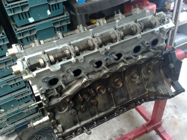
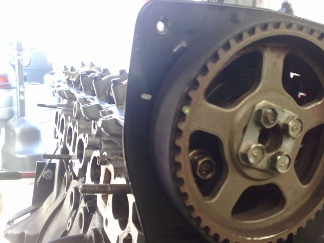
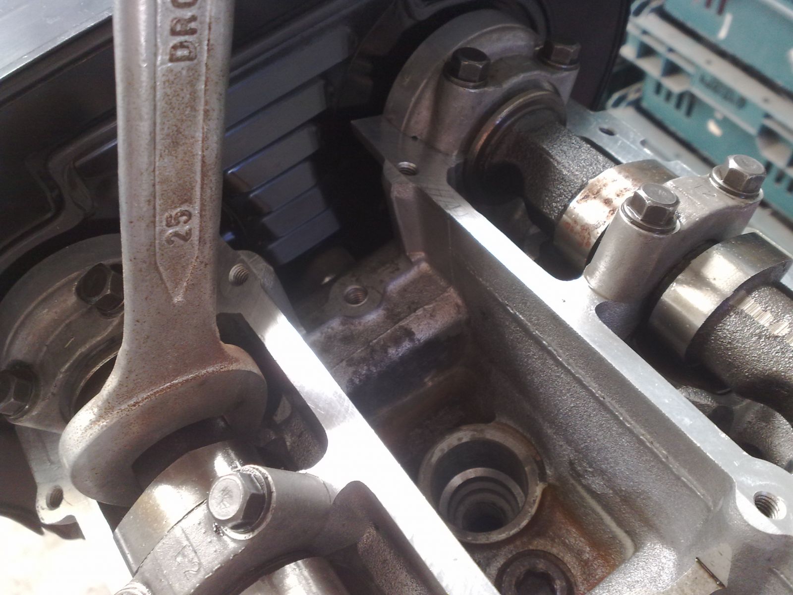
Step 6: Head Disassembly Dissemble the RB25DE HeadFirst things first here. It's so easy to snap a camshaft in half if you try and do this the fast way. If you take your time and follow the steps I post below, you will eliminate entirely any chance whatsoever of turning your cams into butt plugs for some sick twink. I've tried the quick and easy method once and snapped a cam in the process, and since I've taken the extra few minutes doing it properly, it's never happened since.
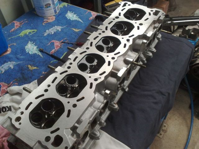
Firstly, lay a bunch of rags out on your workbench equal to about the length and width of your head, and place your head (not your skull (or your cock)), cams up on the rags. The reason for this is that some of the valves are in the open position and we don't want to do any damage while we remove the cams.
Now for the long laboured part of the removal process. If you look at your cam and caps, try to envision the diagram below as representing them, F denotes Front.
01 02 03 04 05 06 07
F
01 02 03 04 05 06 07
The numbers represent the bolt holes for each cam cap. Can you see that yet? If you don't, go have a wank to clear your mind, and then come back and have another go.
After you've returned from tossing off furiously to Kate Beckinsale, have a look again at the diagram below and envision the sequence that we’re going to remove the cap bolts.
01 02 03 04 05 06 07
F
14 13 12 11 10 09 08
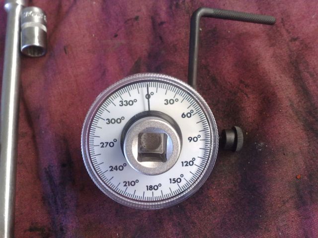
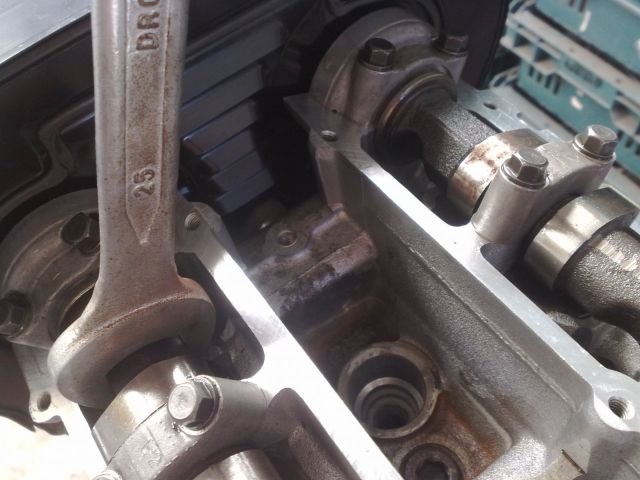
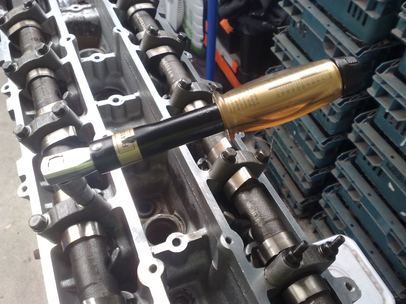
Now the important part, you need to undo the bolts a half turn at a time in the sequence shown above. Putting it in terms an 8 year old can understand, undo bolt 01 with a 180 degree turn once only , then move on to bolt 02 and undo that one with a 180 degree turn once only, then move on to bolt 03 and undo that one with a 180 degree turn once only, moving along in sequence until you have reached bolt number 14. Now repeat the cycle again, and again, and again, and again until all of the caps are loose and the valve springs have released their tension.
It’s a somewhat tedious process, but believe me, it’s better to do this than to find yourself on your knees in your workshop, holding two pieces of your cam whilst crying like a schoolgirl.
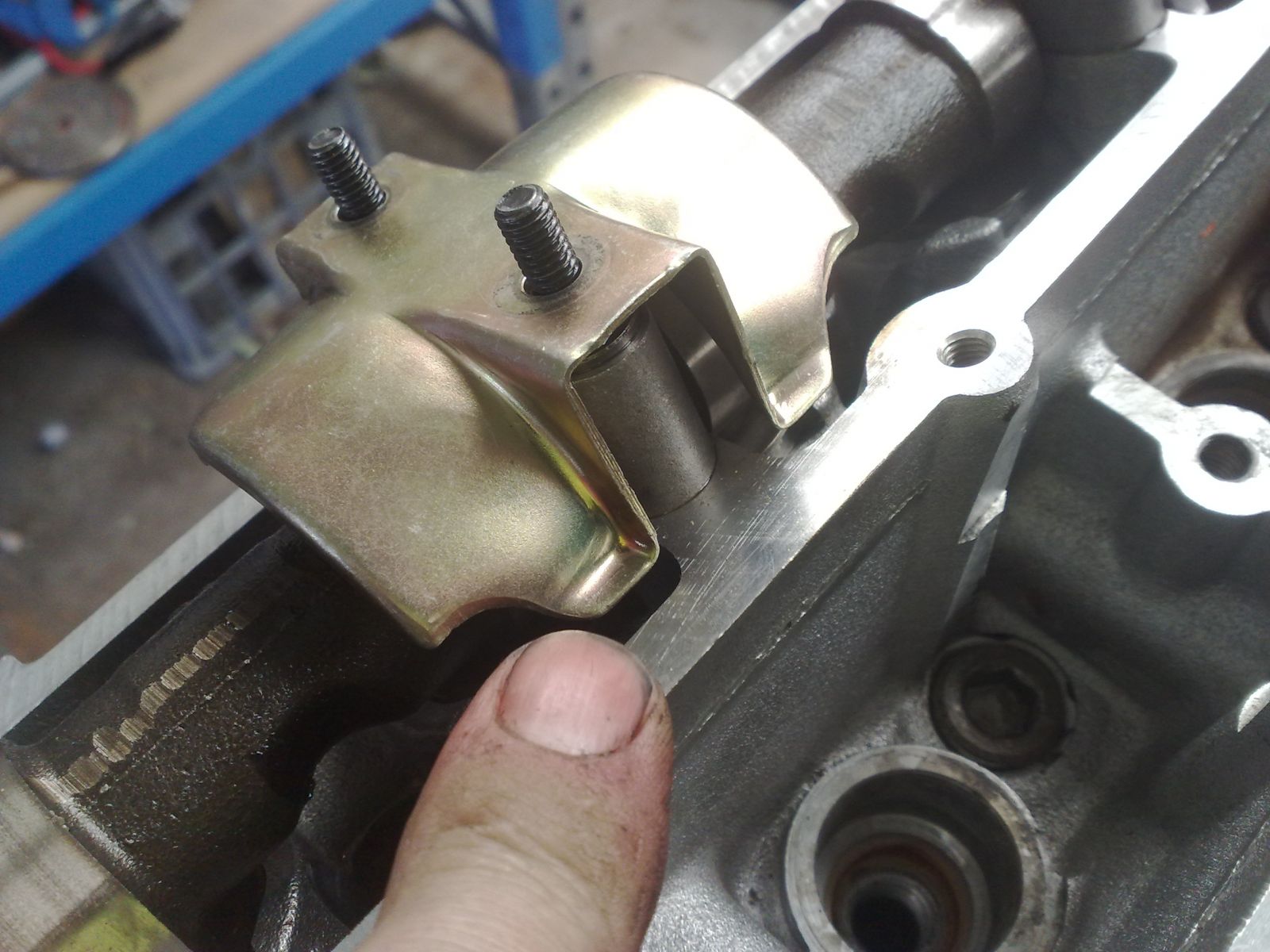
Make sure you have a clear space for some of these components as we proceed with the next steps as we will need to reassemble the head reusing some of them, putting them back in their original places. The parts we will be reusing are the cam caps, lifters, and valves.
Remove a cap at a time and place it down on your workbench in sequence the same way as your head is facing. It doesn’t matter whether the front is facing left or right, just as long as you have it all in the correct order and sequence as the head is facing at the time. Also, remember to make sure that the next cam that comes out is placed on the workbench in the same position as the head is facing, above or below. As an example I have made another diagram showing you what I’m on about. Obviously, C denotes Cap, F denotes Front.
C C C C C C C - Inlet Side
F
C C C C C C C - Exhaust Side
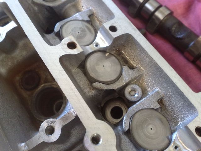
Once you have removed all of the cam caps and cams, it’s time to remove the lifters and place them in sequence along with what we have just laid out. Basically the whole thing will now look a little like this, L denotes Lifter.
C C C C C C C
LL LL LL LL LL LL
F
C C C C C C C
LL LL LL LL LL LL
You can remove the lifter by using your fingers, but if they are a bit too oily, then you can use a magnetic pick up tool to extract them.
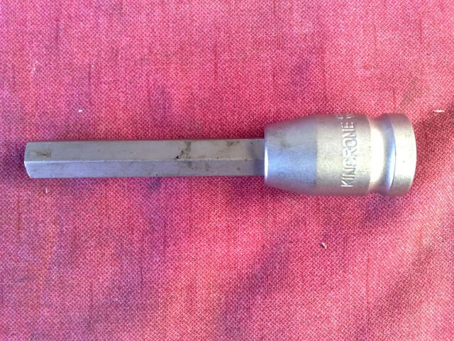
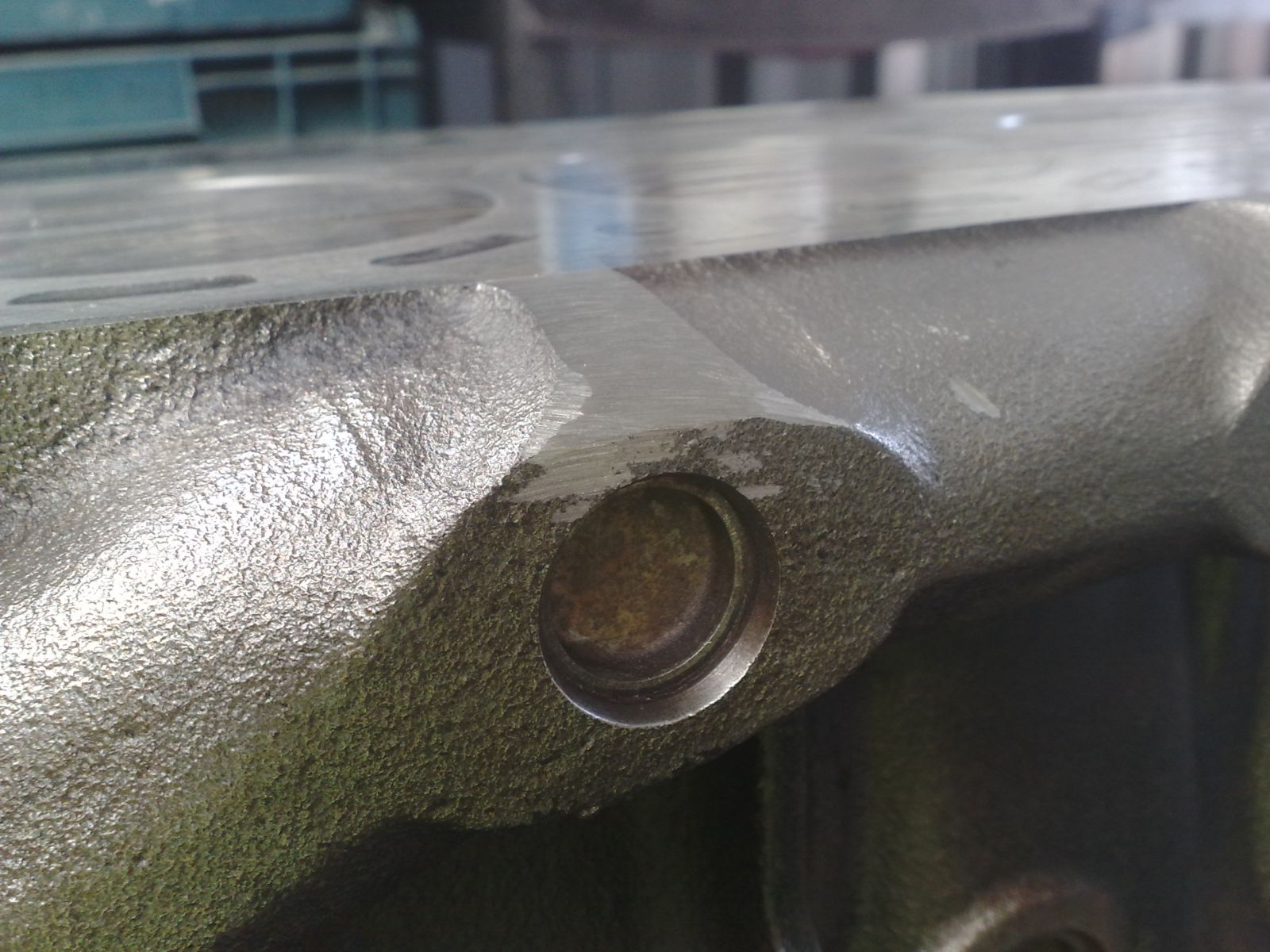
Next comes the valves, springs, and retainers. Get yourself one of these types of valve spring compressors (VSC). This is the type of VSC that will allow entry into a recessed valve head. The old style that Dad used on his 1960 cars won’t work.
Download Full Size Image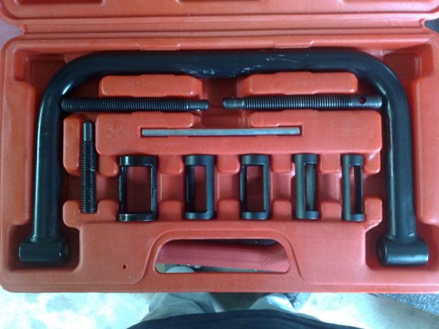
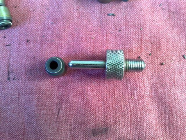
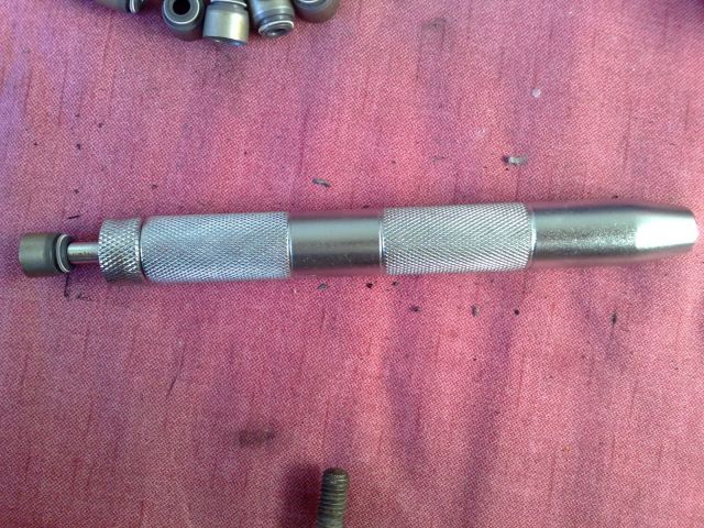
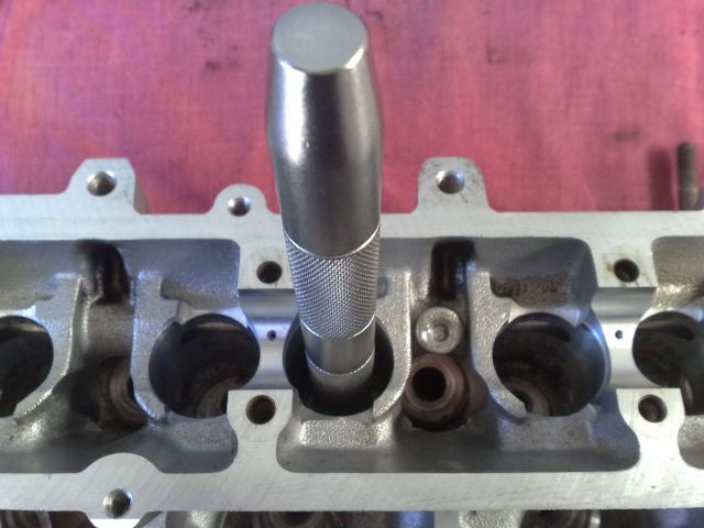
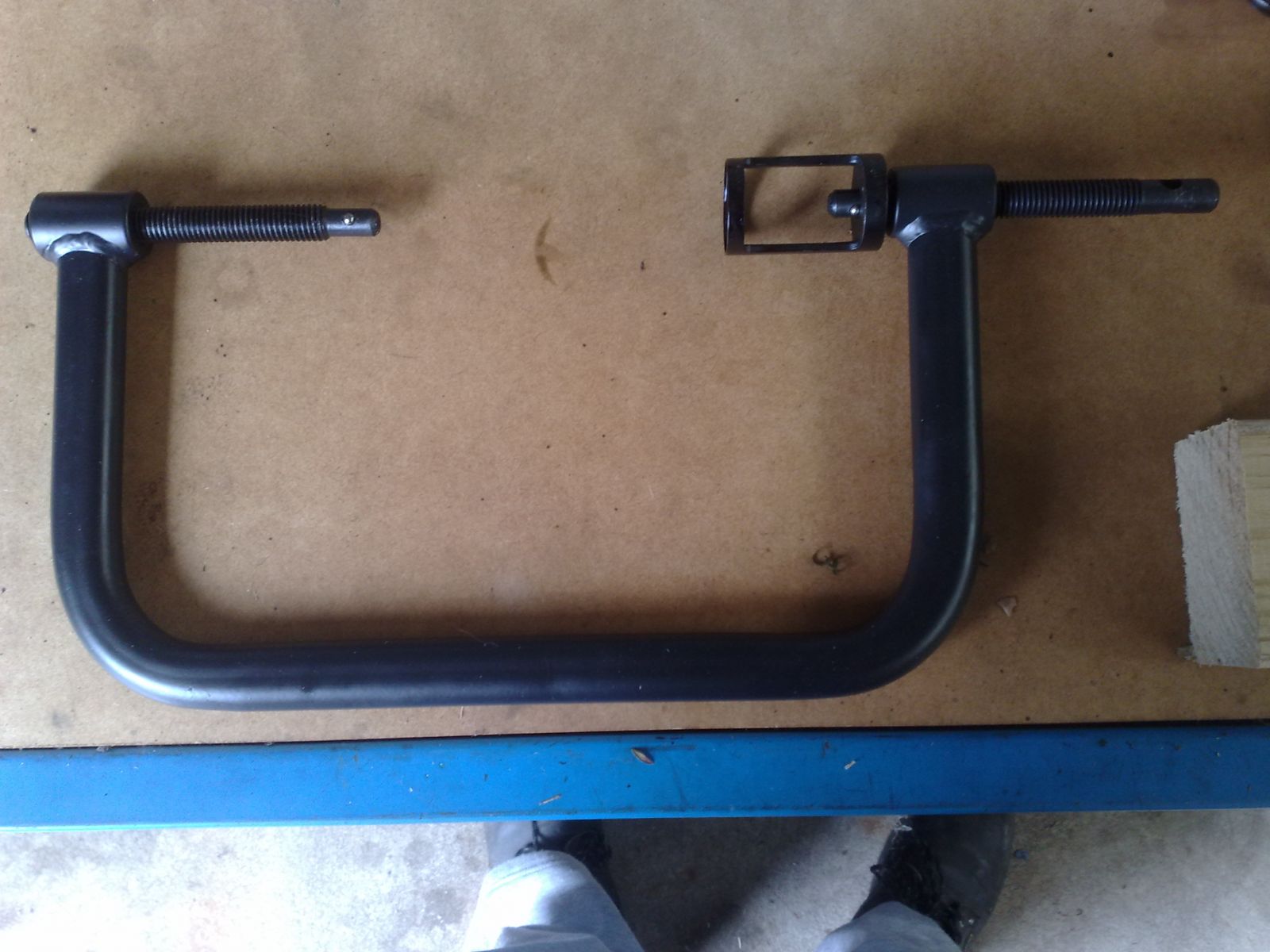
Select the appropriate head for the VSC and put it all together. This is what it should look like assembled and ready for use.
Download Full Size Image
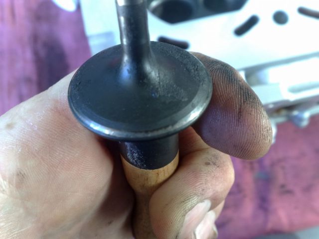
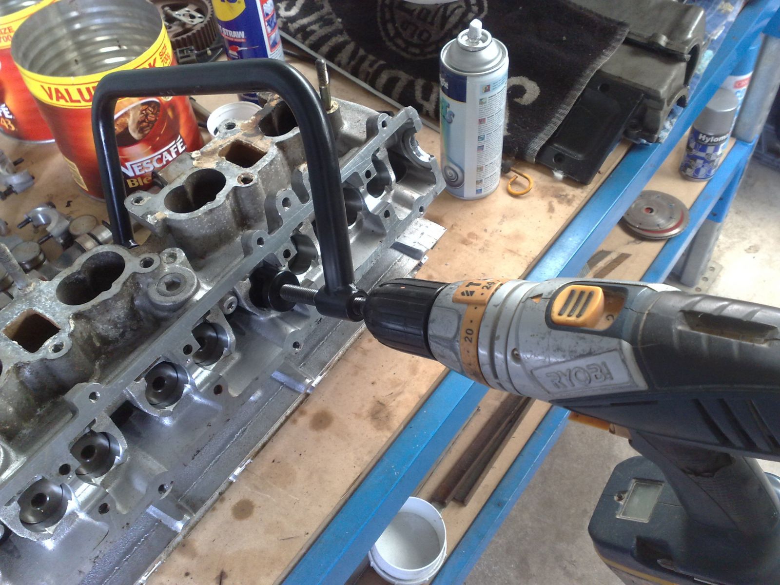
When it comes time to compress the valves, you can either use the little lever that comes with the kit, or do what I did and attach the setup to a cordless drill and make things easier.
Download Full Size Image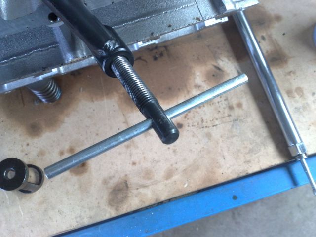 Download Full Size Image
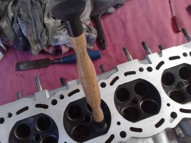
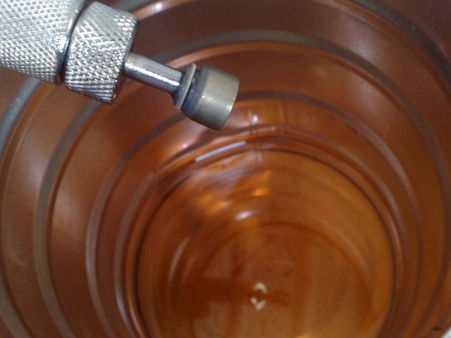
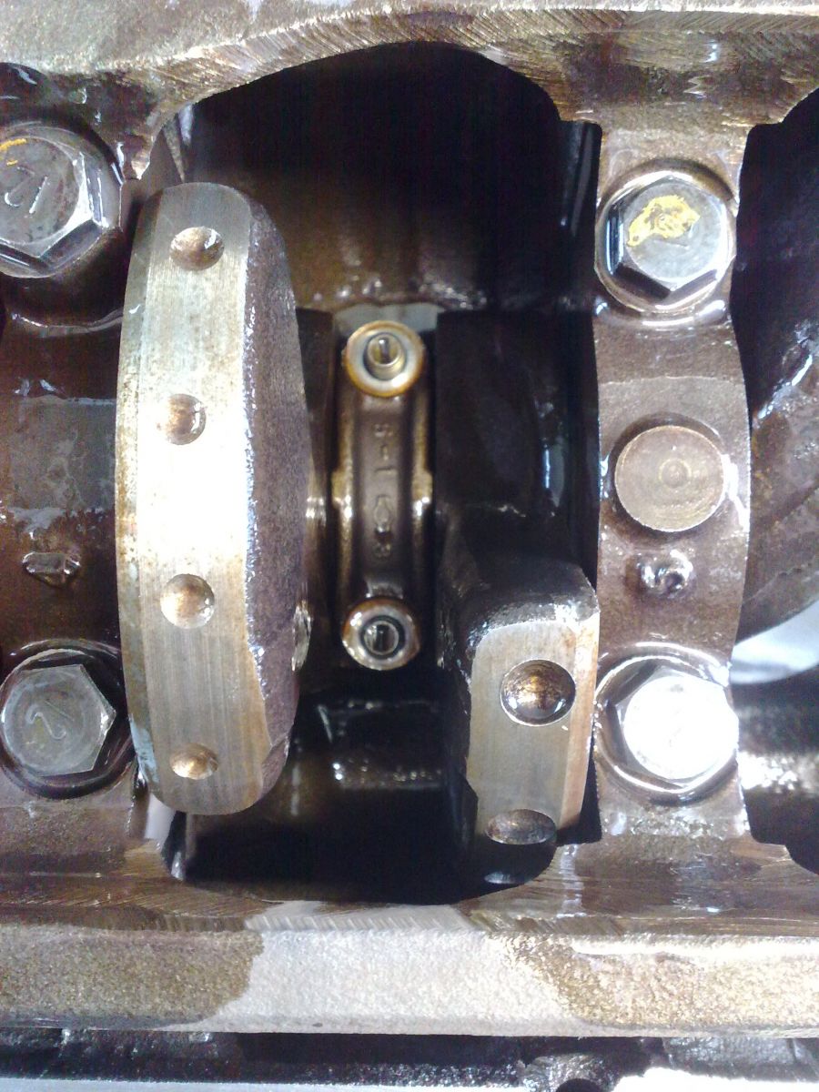
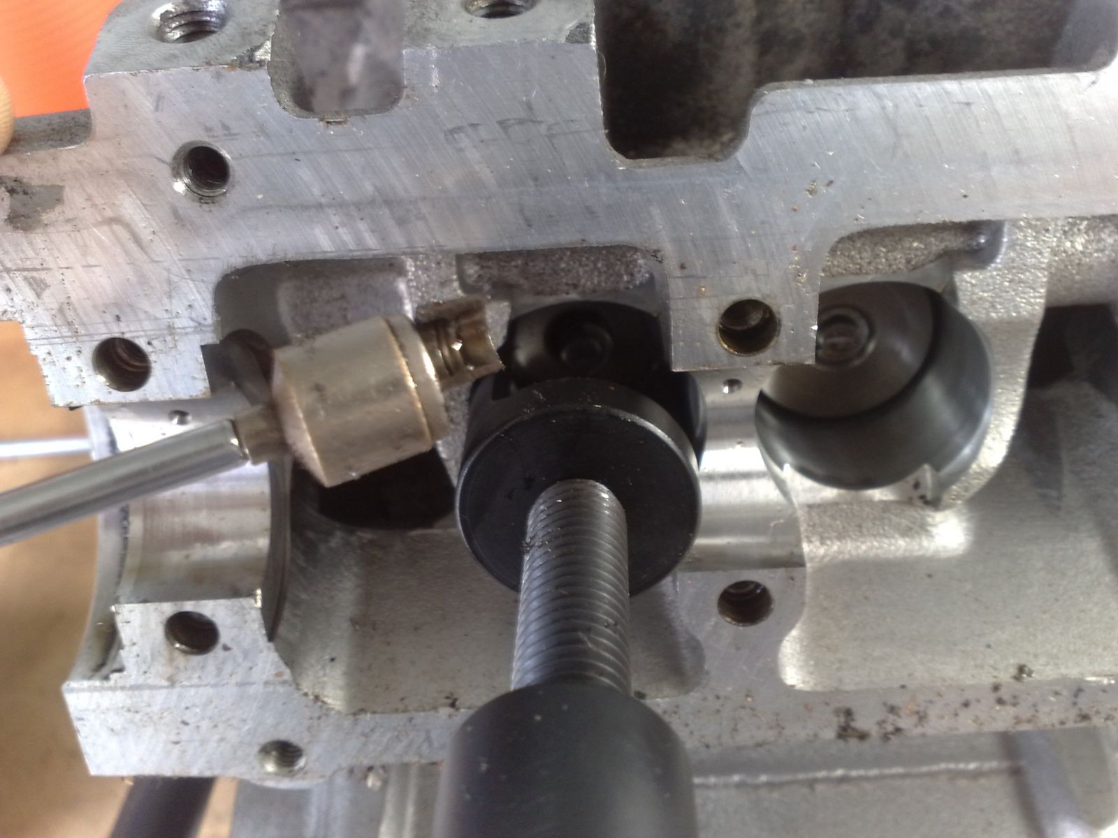
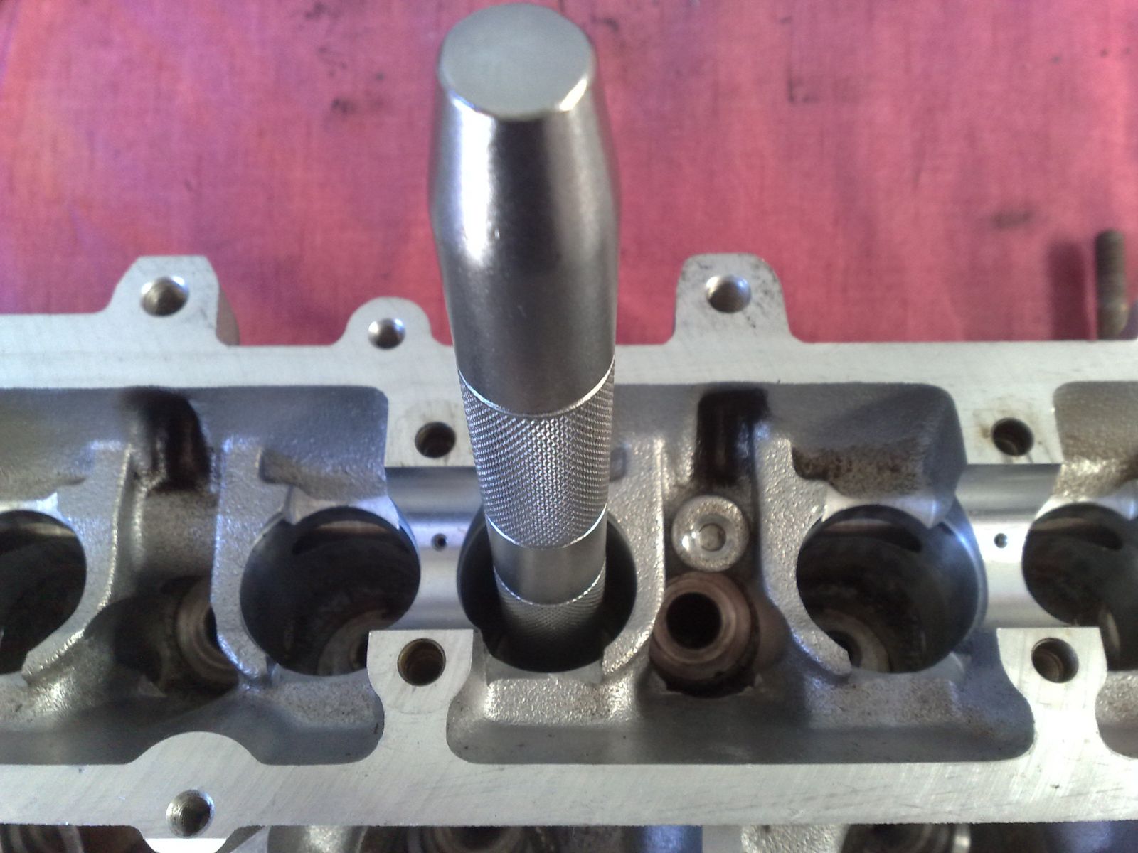
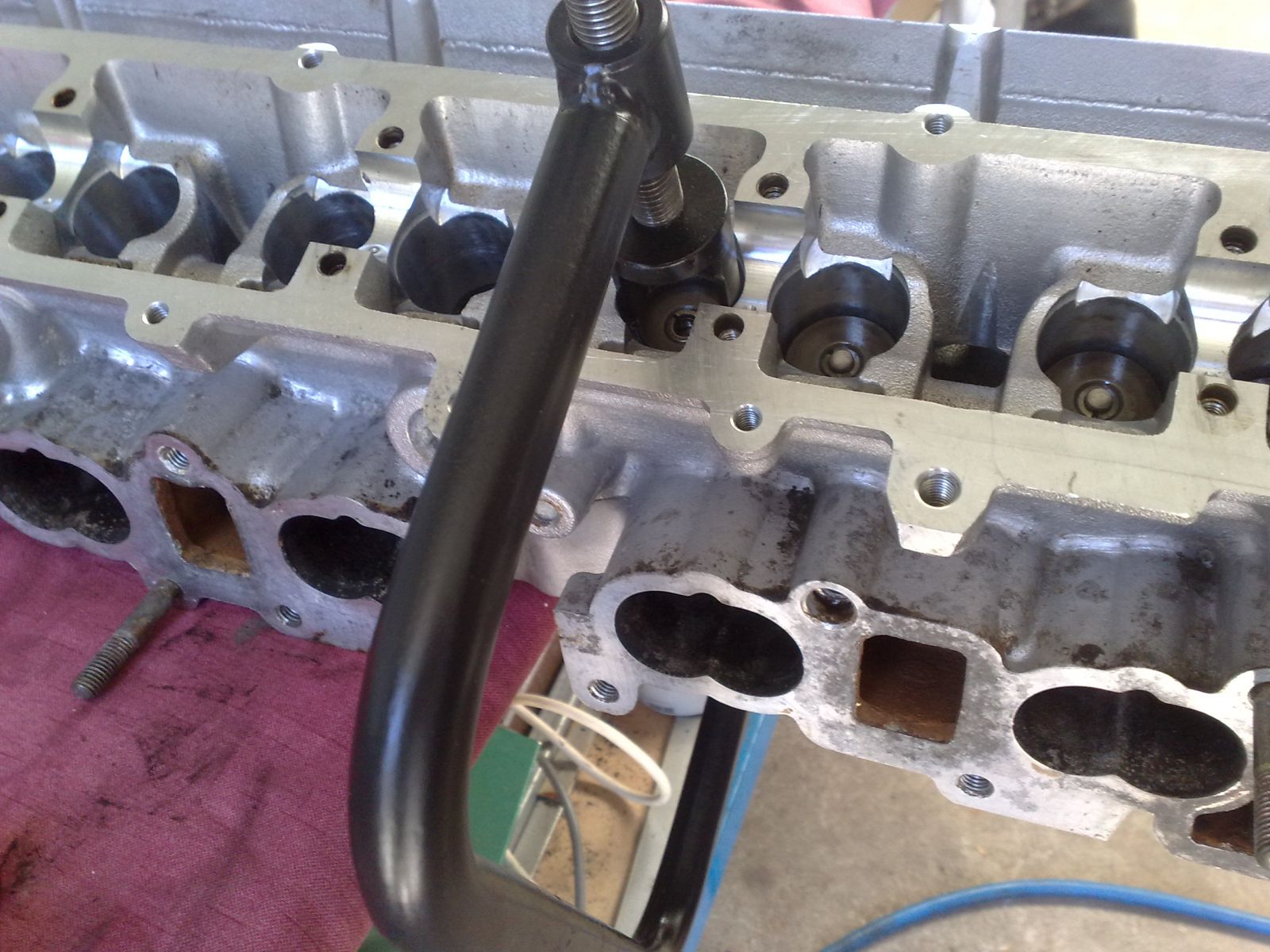
Position the VSC on both sides of the head, it should look like this.
Download Full Size Image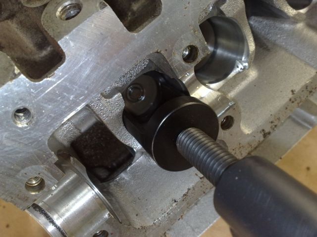 Download Full Size Image
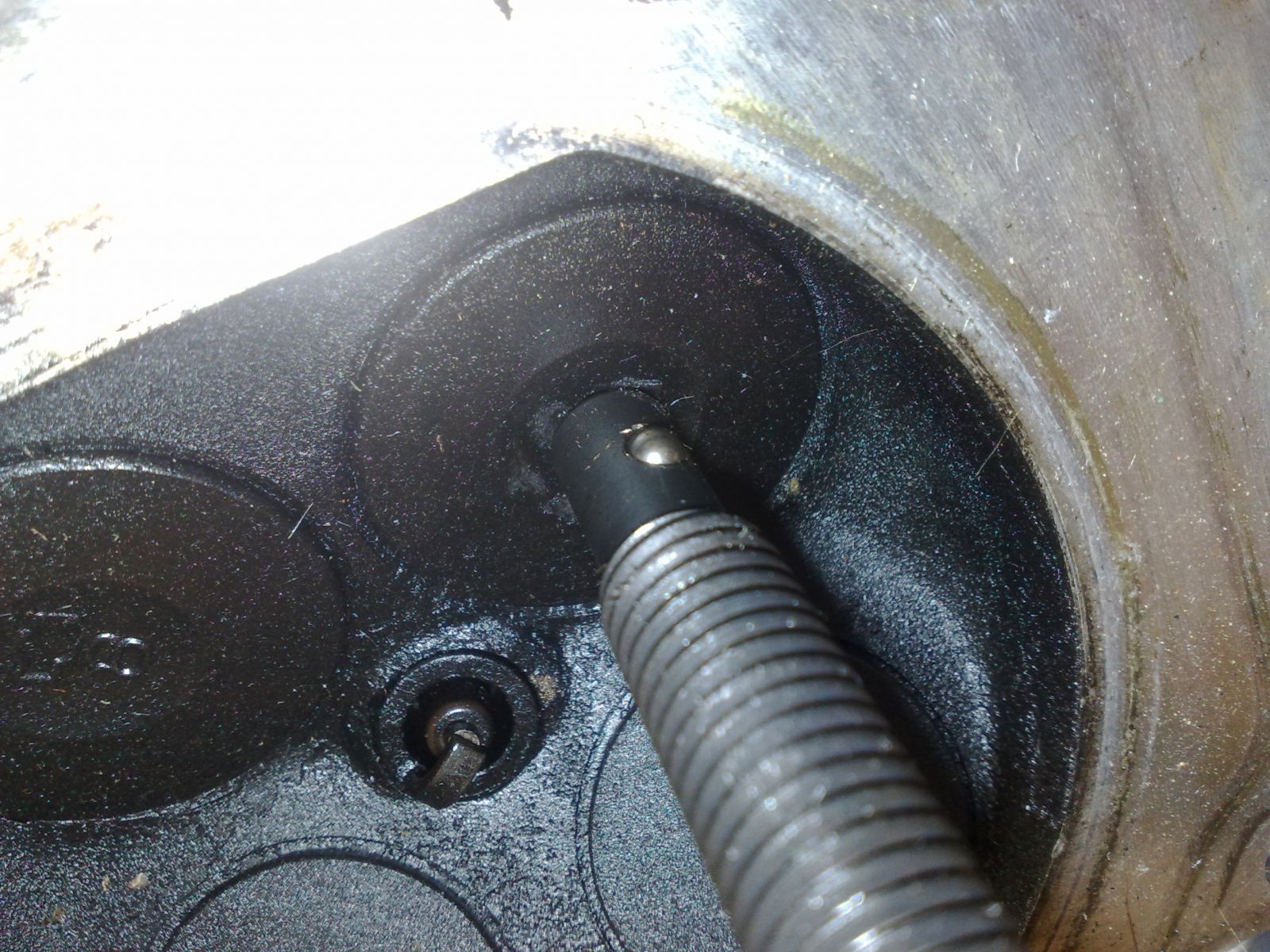
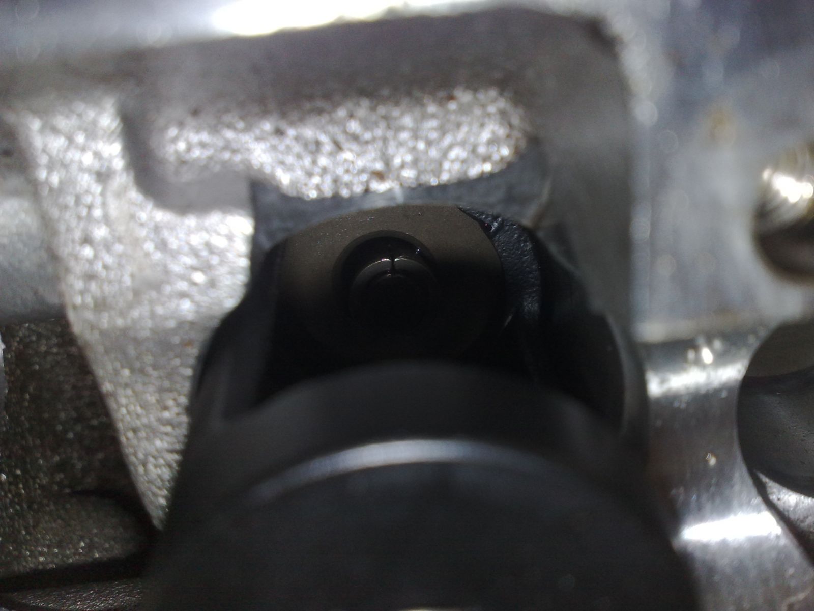
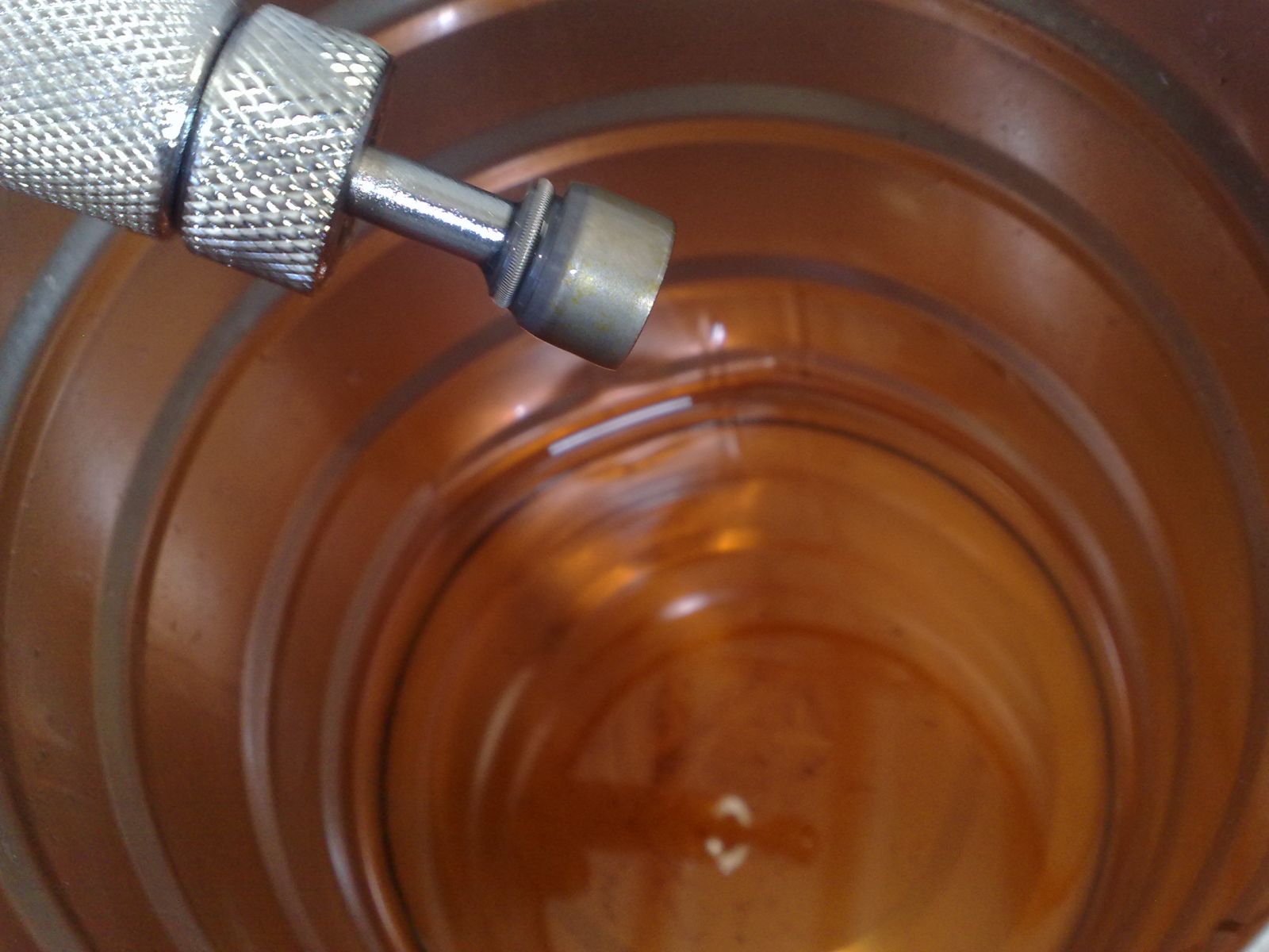
Wind the VSC down until the retainer clears from the collets, it may make a popping noise as you do this so don’t be alarmed.
Download Full Size Image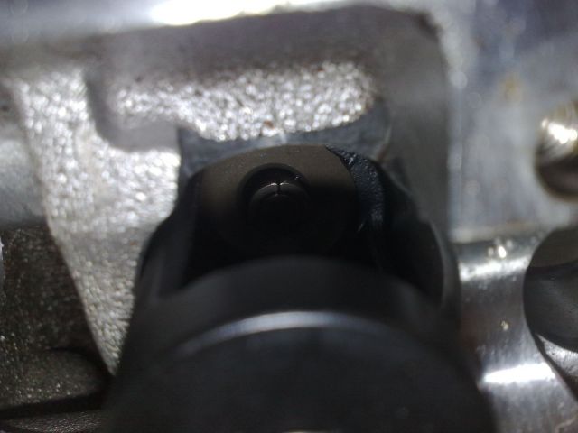
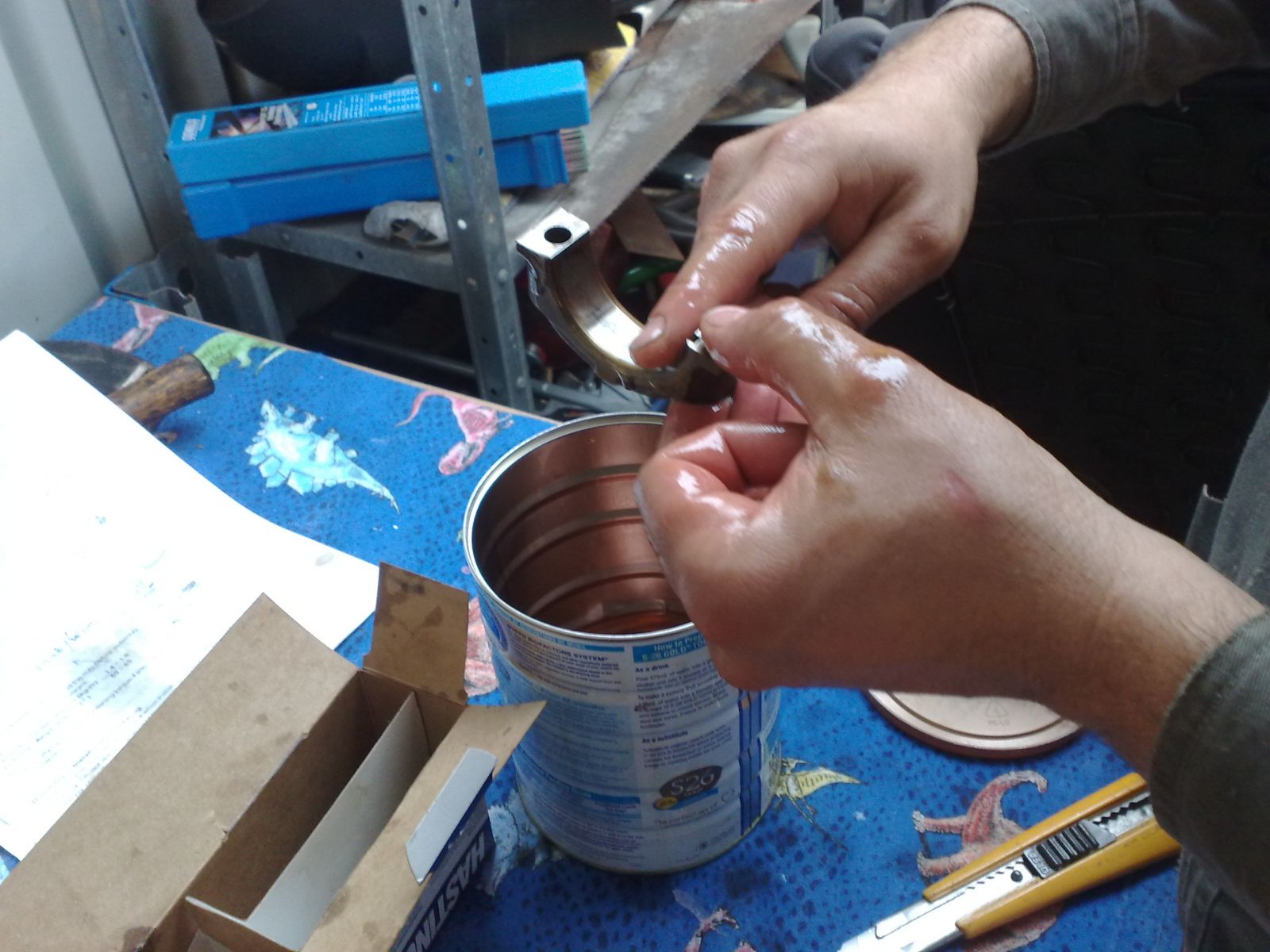
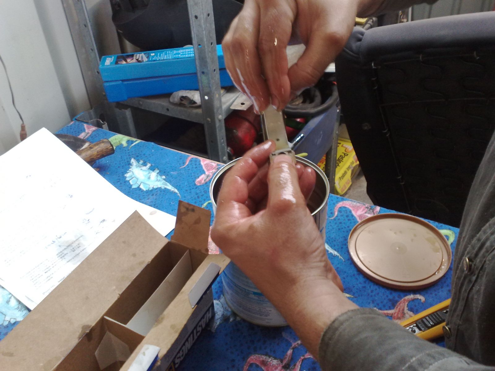
The easiest way I found to remove the collets is by using a magnetic pick up tool. Once you have removed the collets, place them in a small jar with a little bit of oil in it.
Download Full Size Image
If the collets refuse to come out, just wind the VSC down a little more to increase the gap between the retainer and collets.
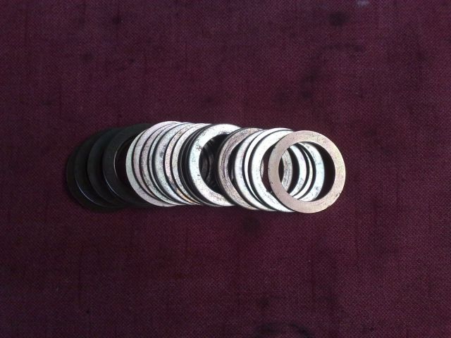
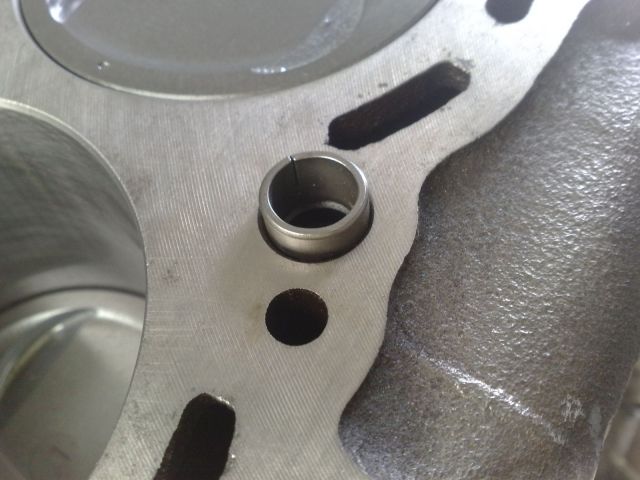
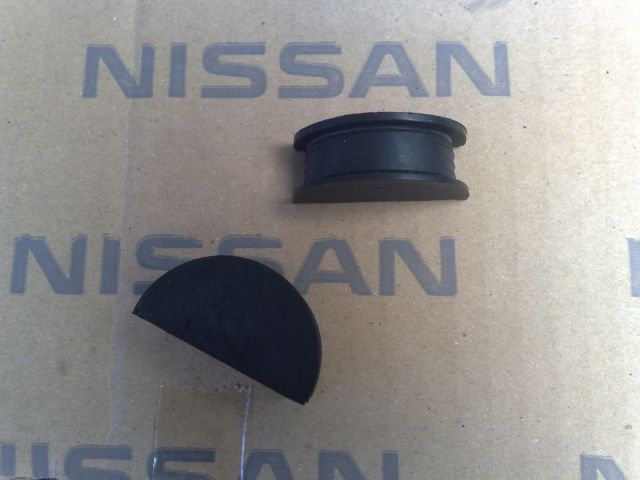
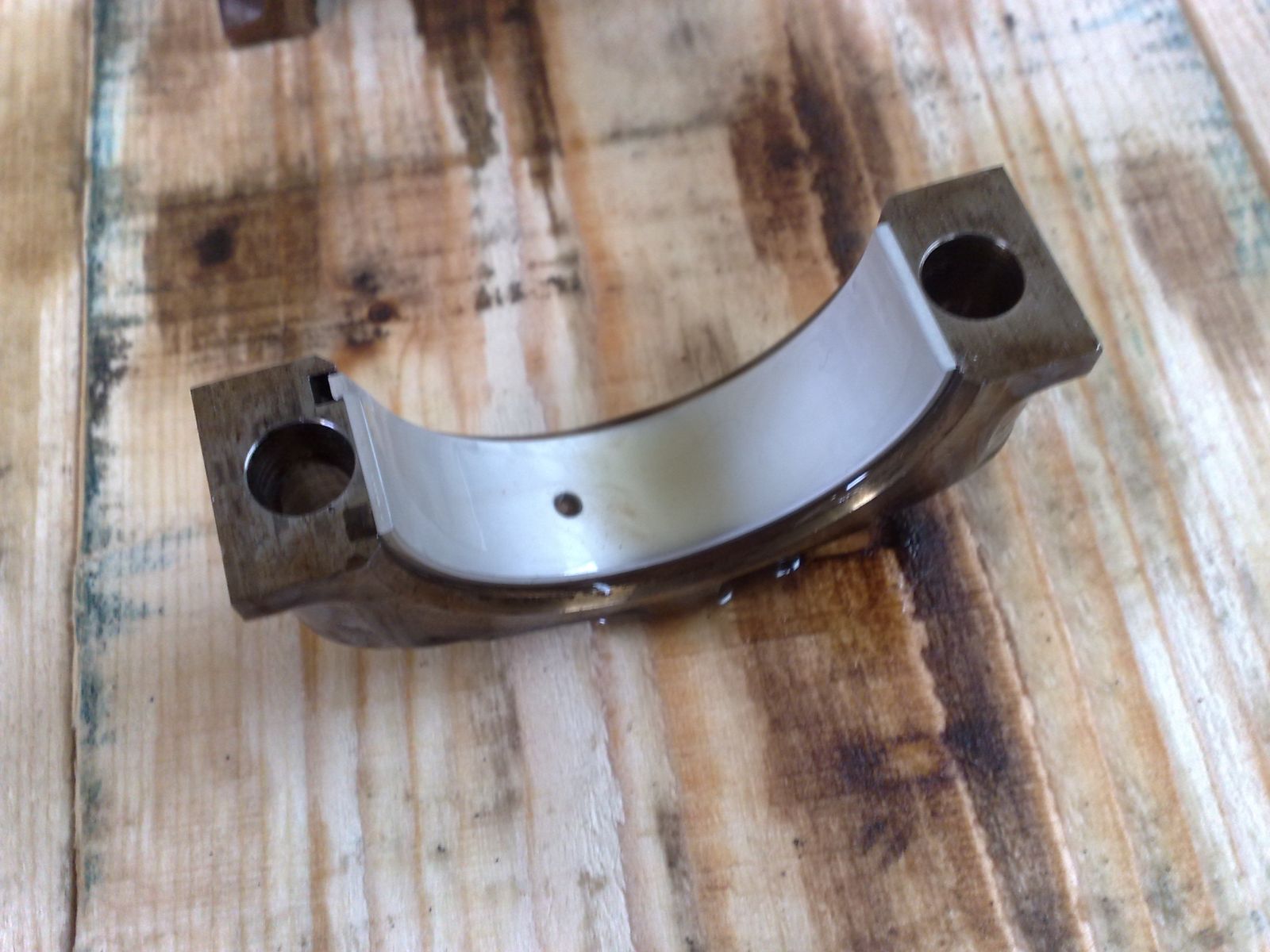
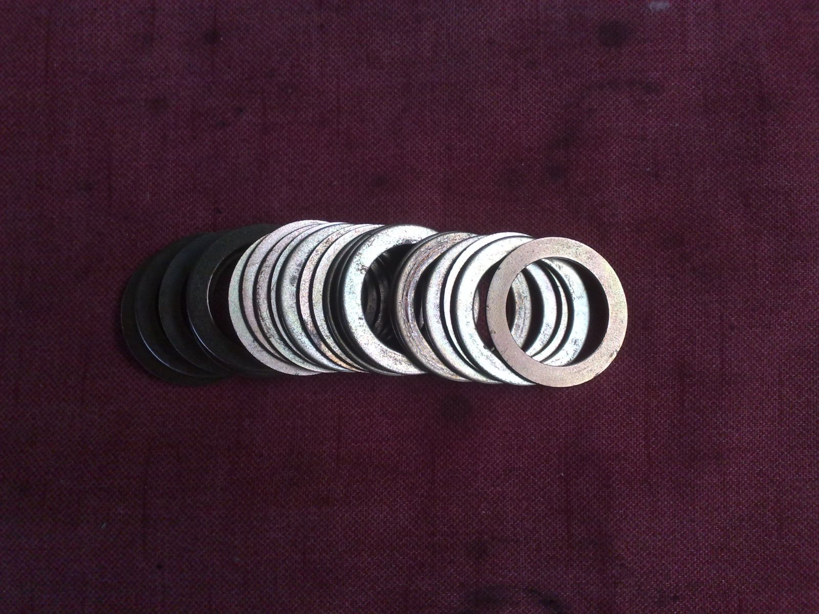
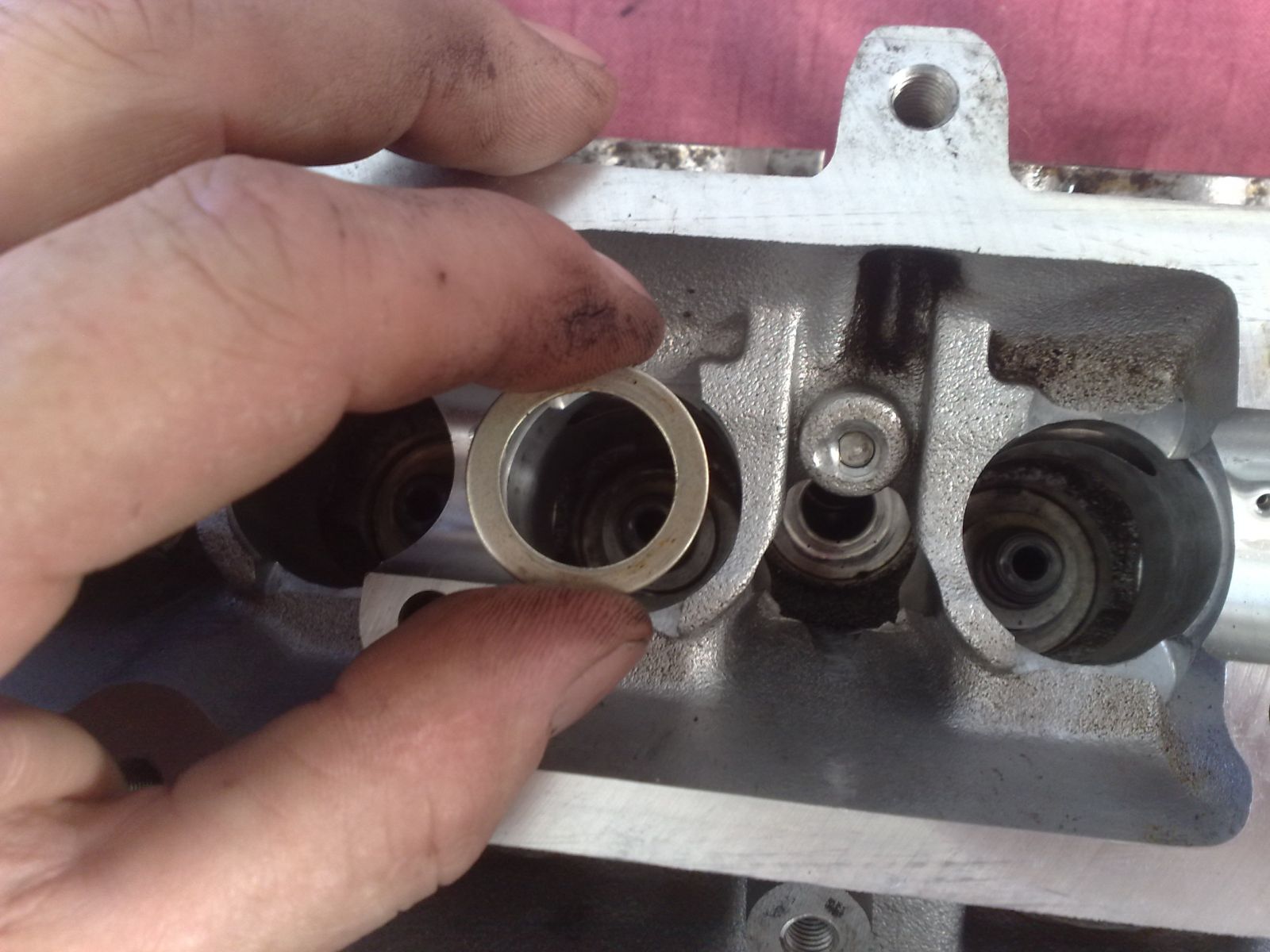
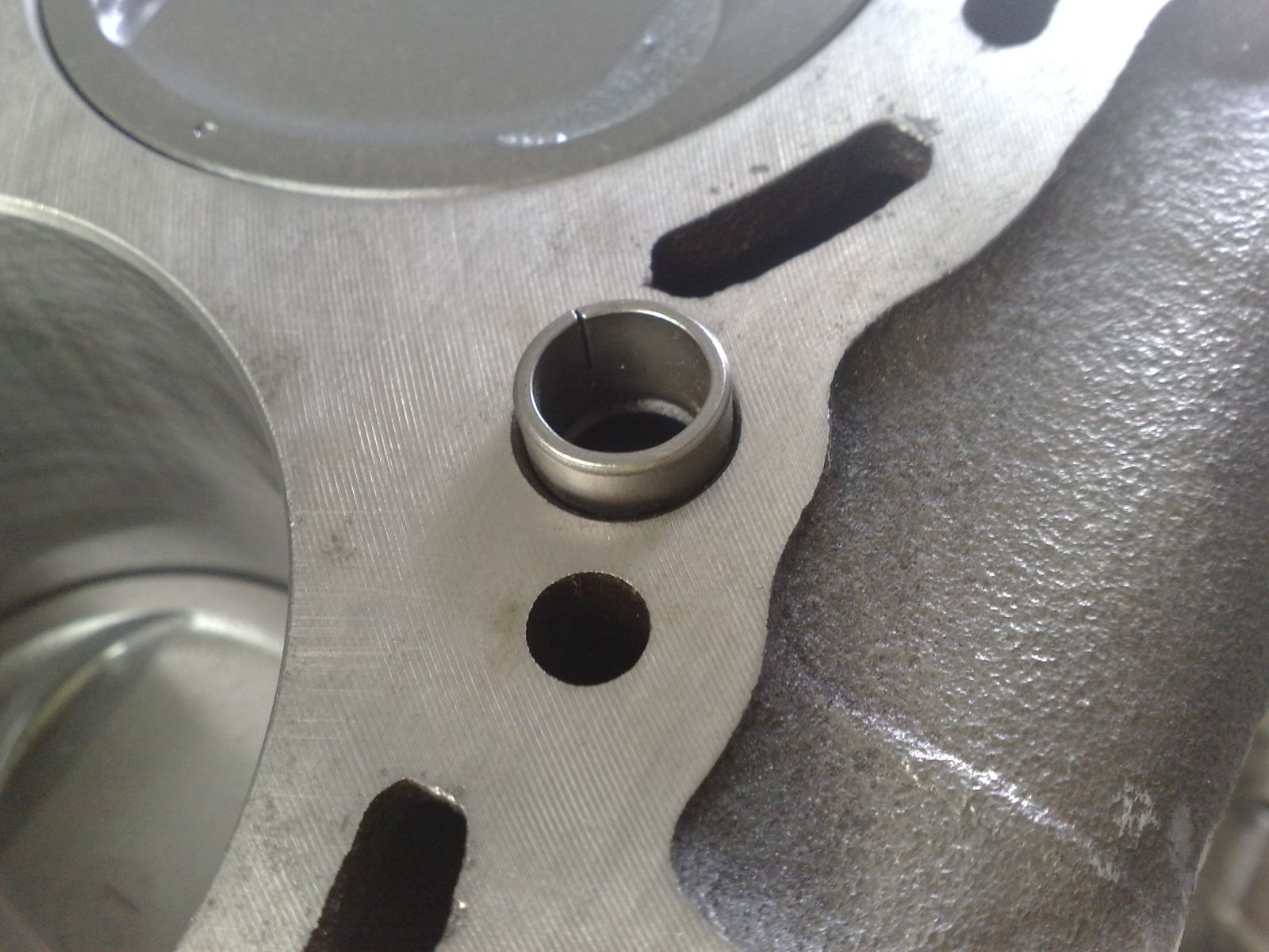
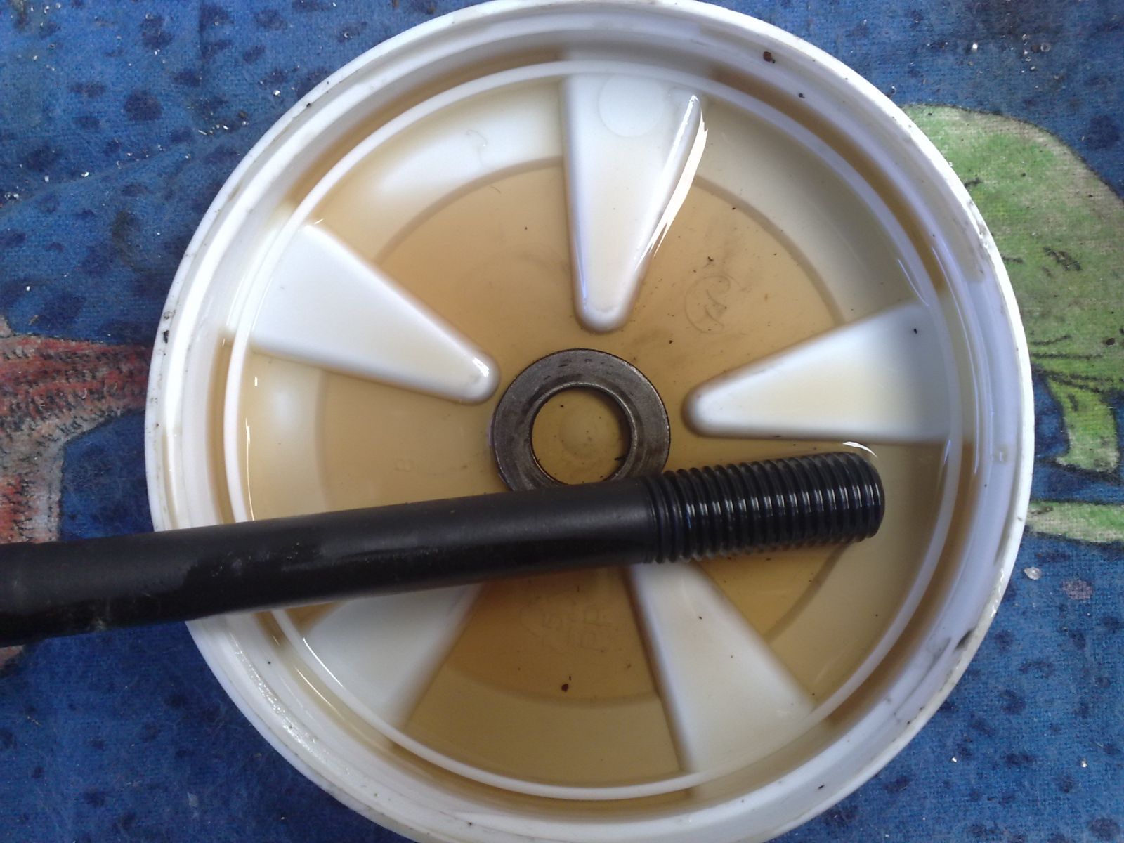
Remove the spring and retainer and pile them up somewhere. We won’t be needing these. Now if you have a look in the recess, you will notice a valve spring washer that the spring sits on, pile these up somewhere with your arrangement as you'll be needing them. What they do is provide a barrier between the head and spring so as not to wear down the alloy of the head.
Download Full Size Image
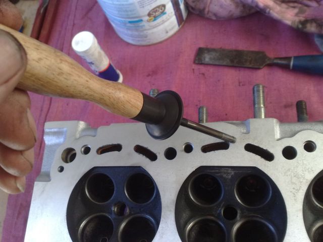
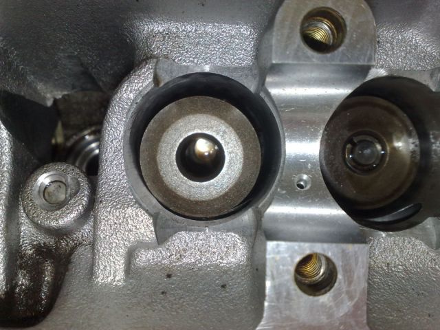
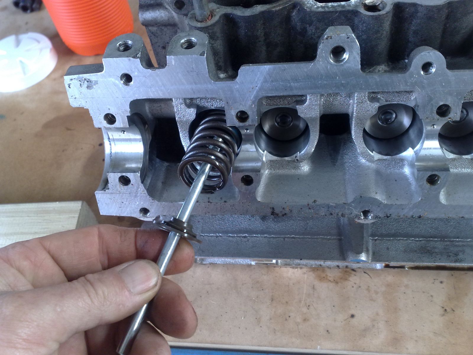
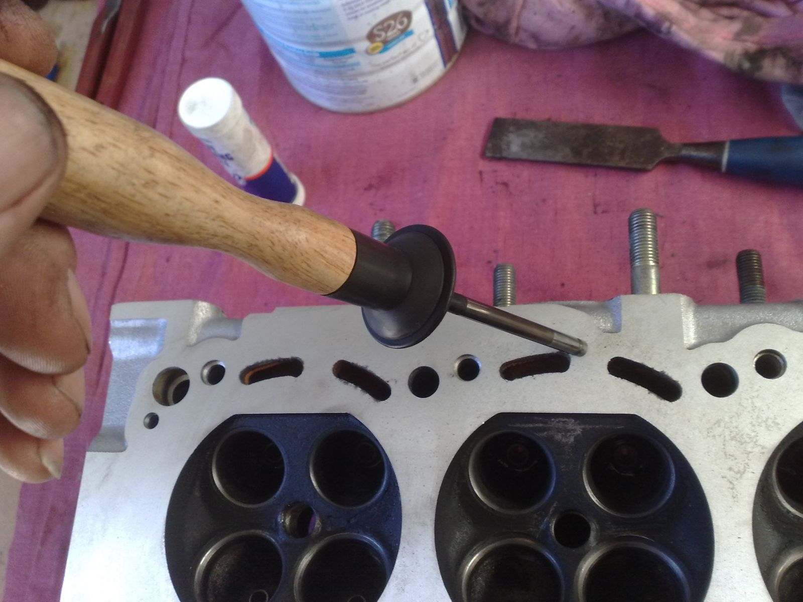
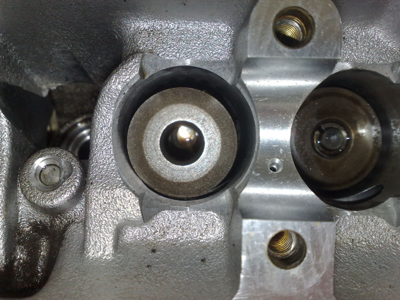
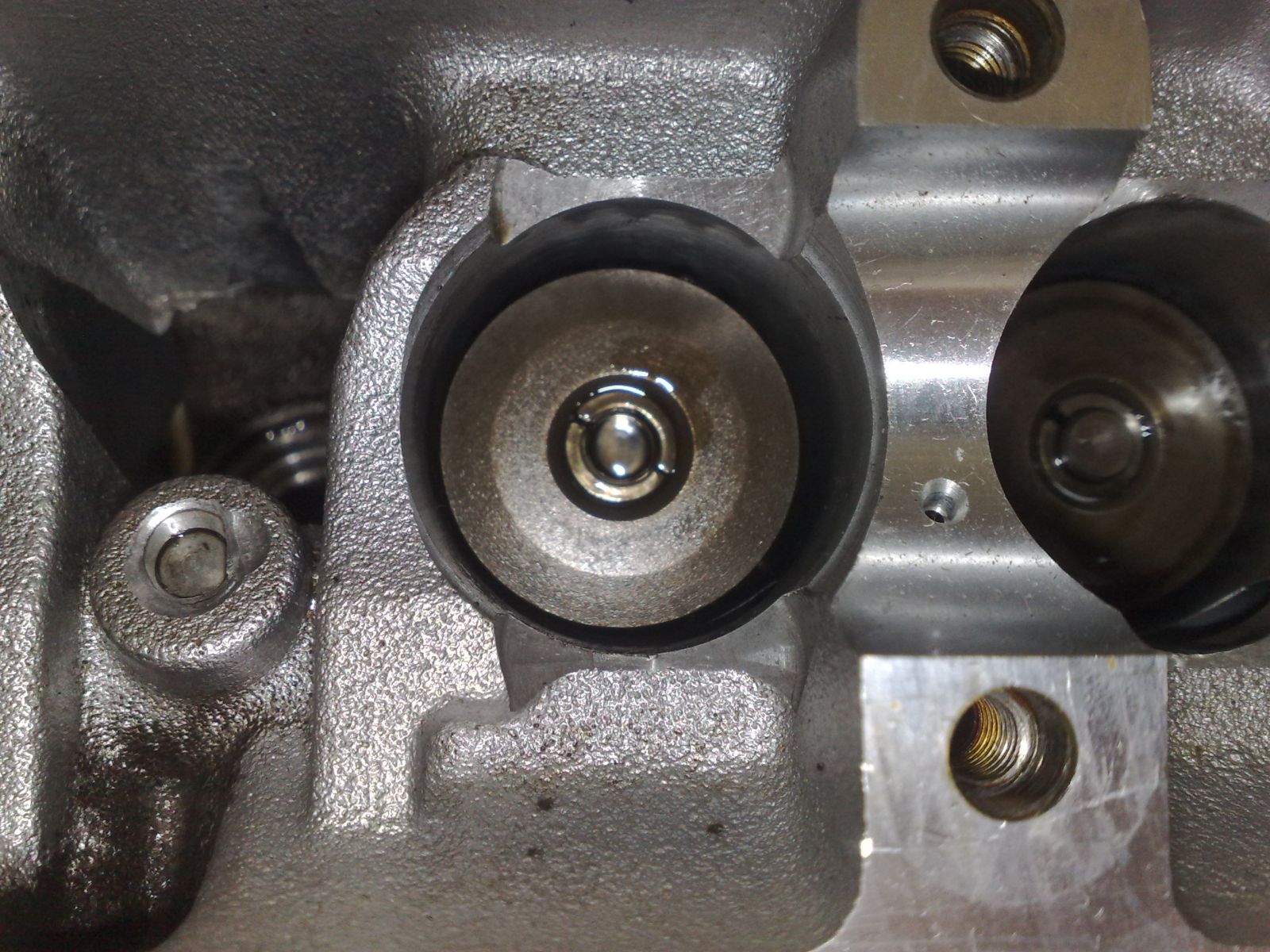
Poke your finger into the recess where the spring used to sit and push the valve through enough to grab it and slide it out. These now need to join the nice little arrangement that you have made on your workbench.
Download Full Size Image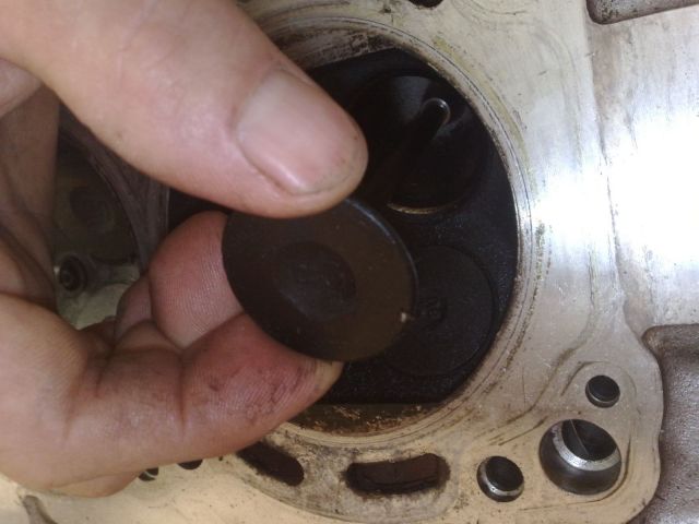
Just in case you need me to remind you, these need to be kept in sequence. A new diagram is now needed to show you how it should all look, V denotes Valve.
C C C C C C C
LL LL LL LL LL LL
VV VV VV VV VV VV
F
C C C C C C C
LL LL LL LL LL LL
VV VV VV VV VV VV
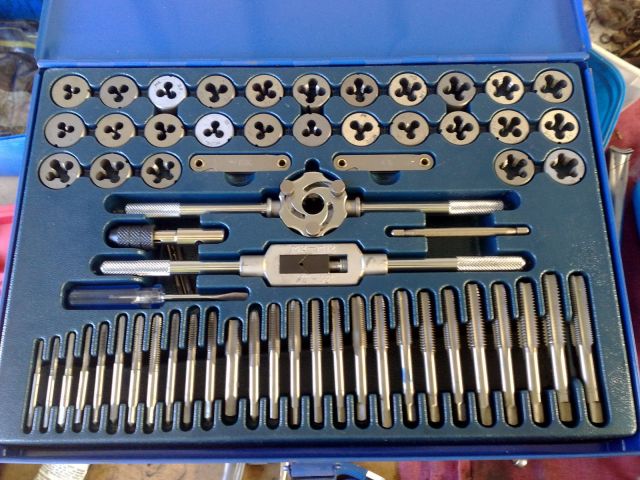
Now you’ll need to remove the old valve stem seals. Don’t be a skimpy prick and think that they’re okay, you’re here, do them. Get yourself a valve stem seal kit (VSS), it will look similar to this one I have.
Download Full Size Image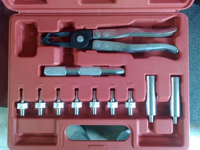
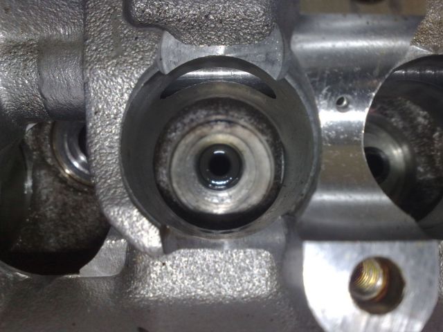
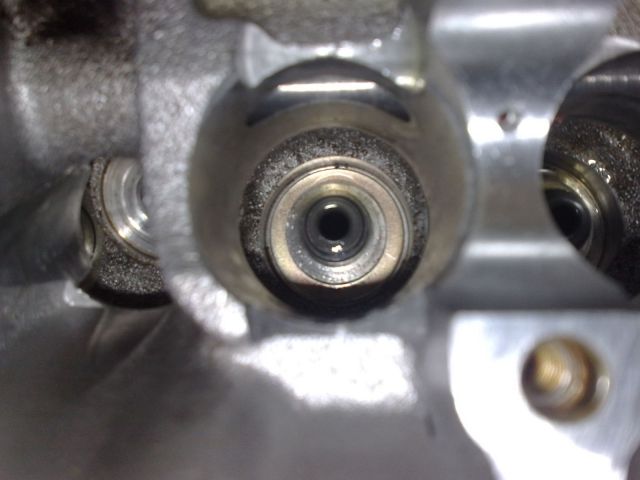
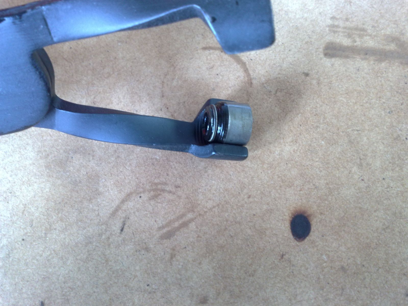
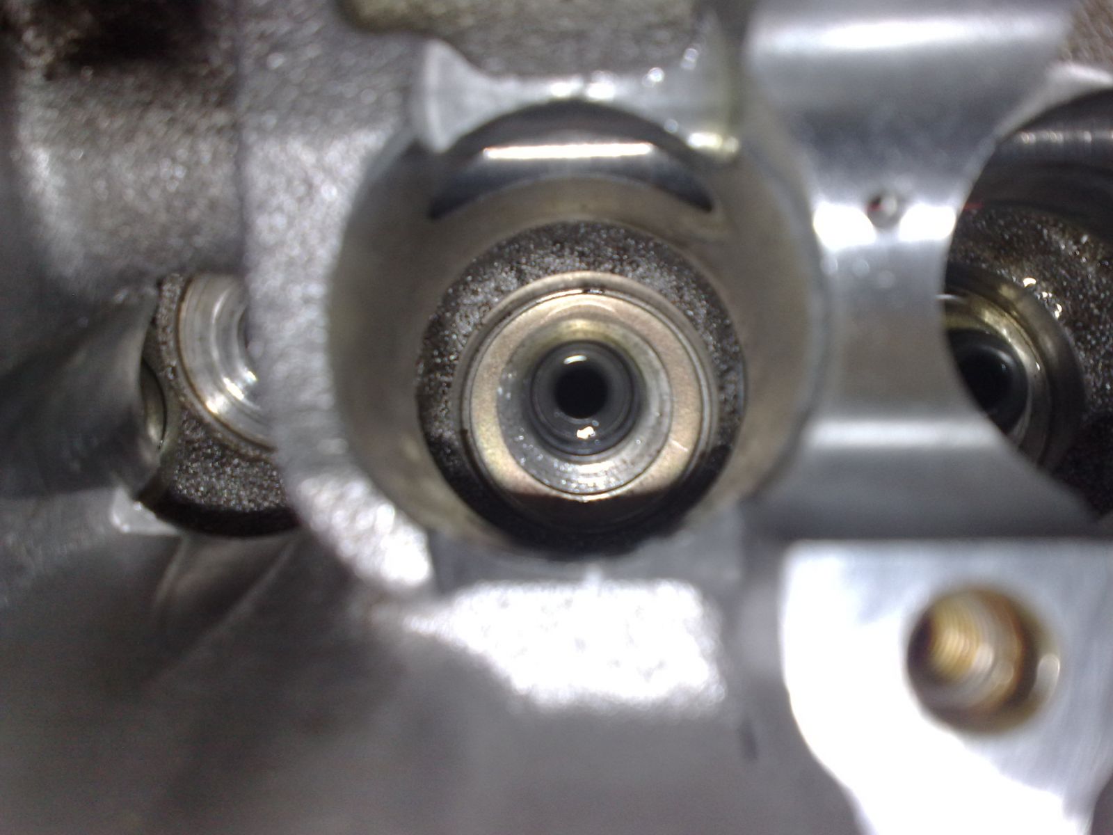
Grab those plier looking things which is the VSS extractor and have a look in the spring recess, you’ll see the stem seal.
Download Full Size Image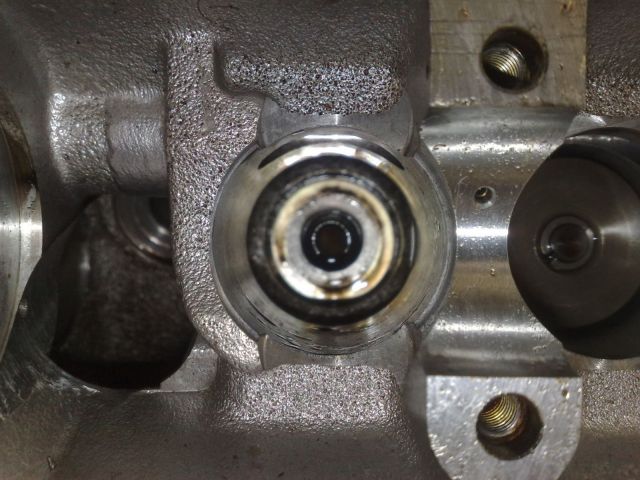
Stick the extractor into the recess and get a lock on the stem seal. Hold the head with one hand, and use the other to twist off the seal using a side to side motion while pulling upwards. Be careful not to look over the head as you do this because when the seal comes out, you’ll end up punching yourself in the face.
Download Full Size Image
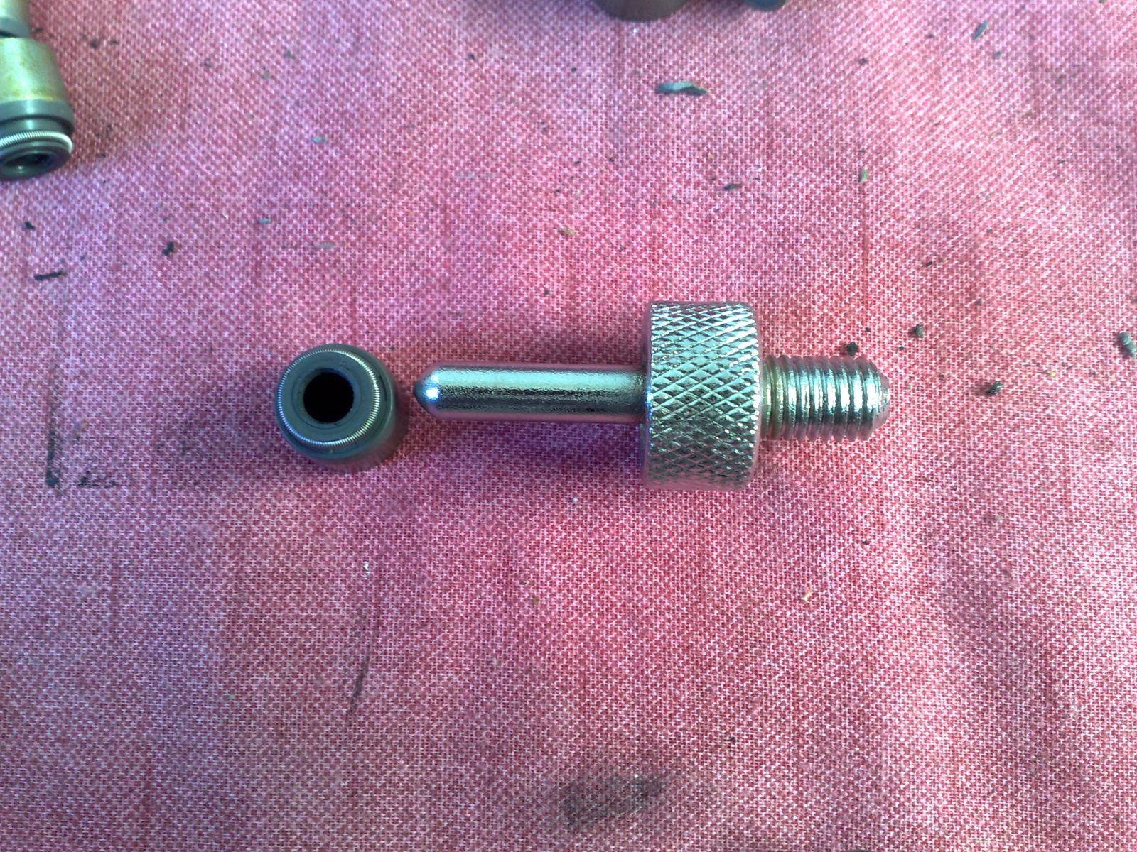
This is the stem seal once extracted.
Download Full Size Image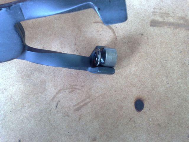
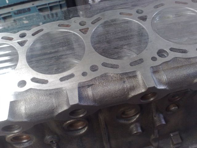
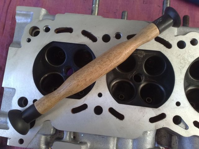
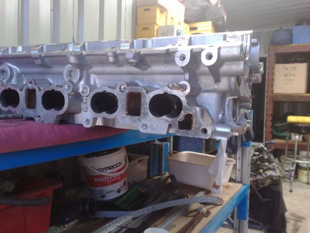
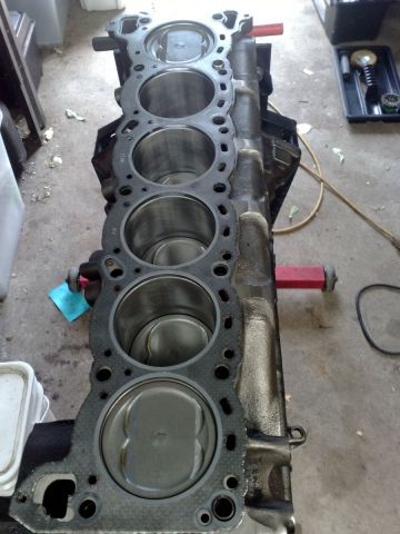
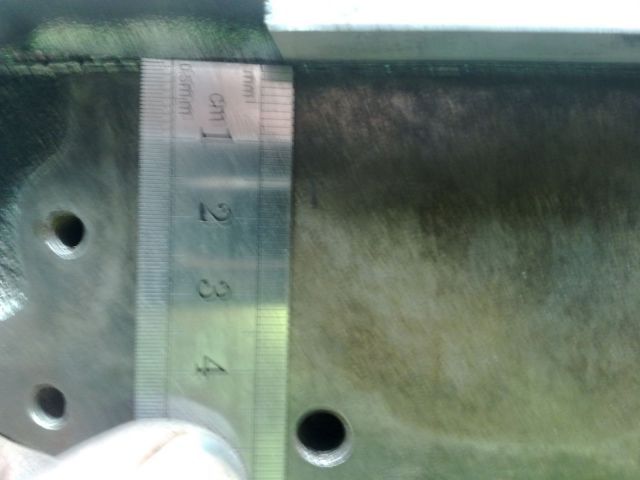
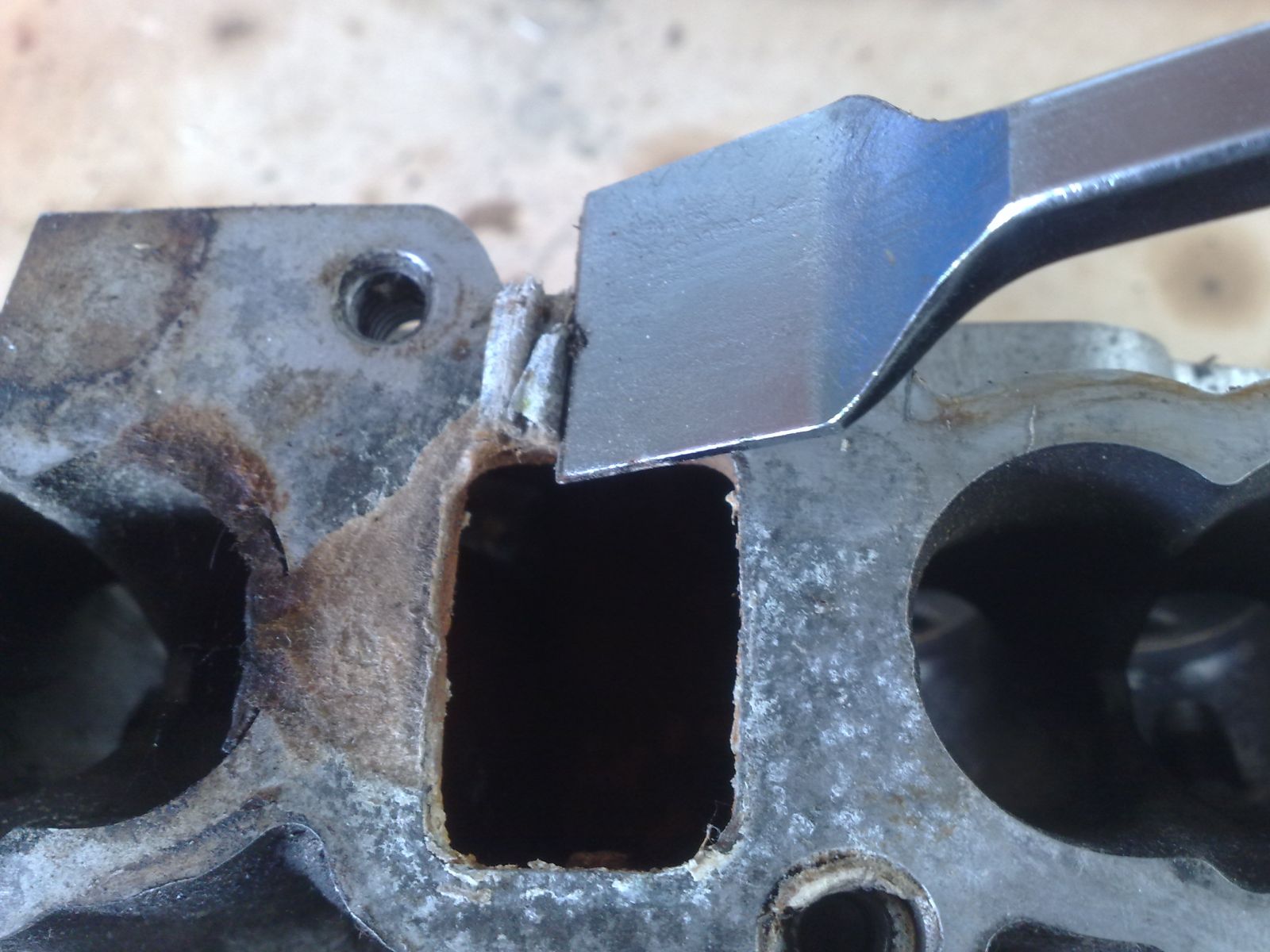
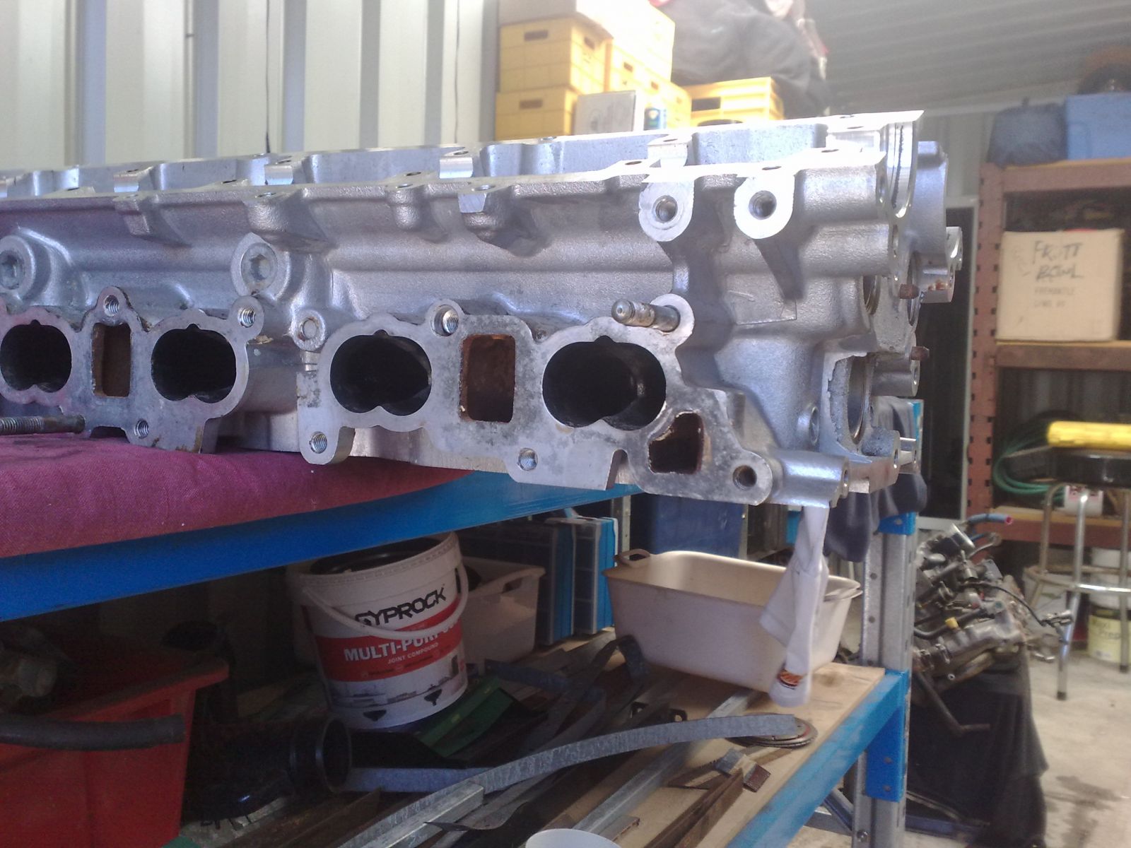
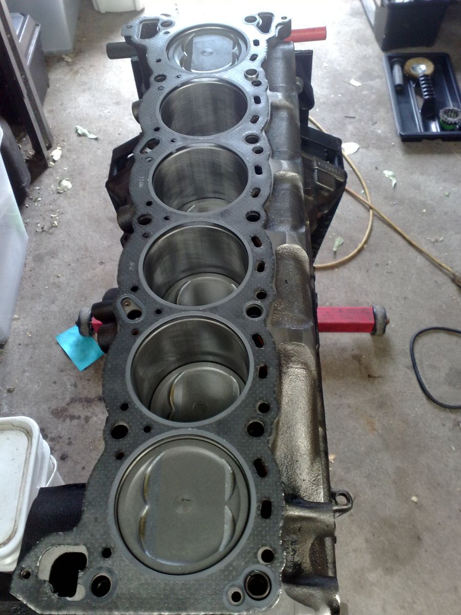
Now all that’s left to do is to scrape off all of the old gasket remnants before sending the head off to be decked.
Download Full Size Image
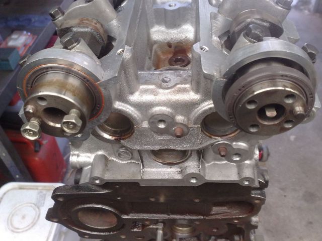
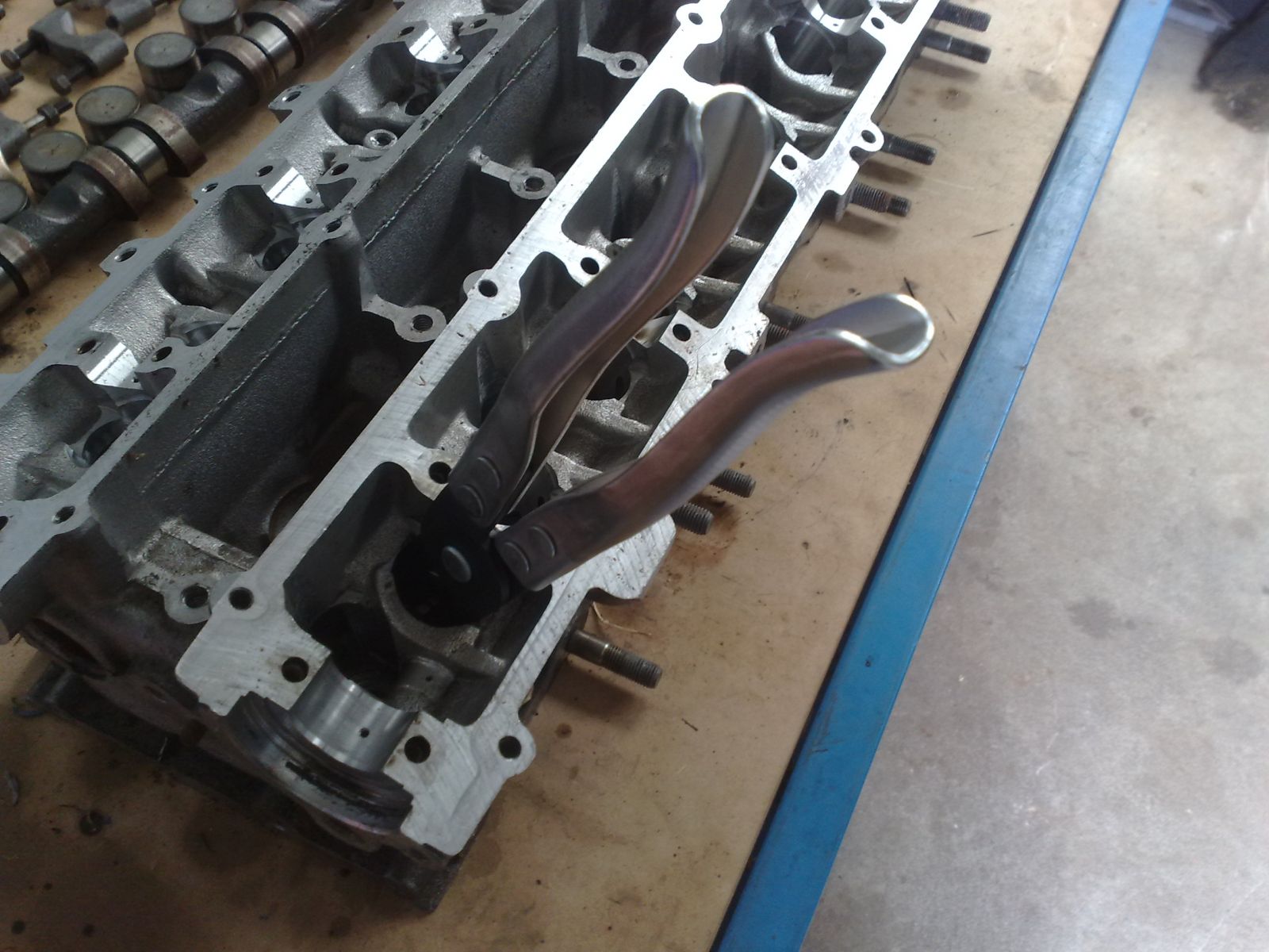
You should be left with the 25DE cams, valve springs and retainers. Either throw them away or sell them off (good luck with that one).

 Sign In
 Create Account


 Back to top


