
 Sign In
 Create Account
I've decided to post up my engine rebuild with a step by step process for those of you who need to do the same thing. There wasn't enough information out there about the car, being an import and all, but I've persisted with a lot of enquiries and research and I've got what I need. Hopefully this will save you the time trying to get all of your facts together and relieve some of the stress.
I'm going to assume that you have a reasonable knowledge of engines so you'll notice the absence of a breakdown guide. Taking things apart is easy, putting it all back together correctly is the crucial part.
Two things to take note of while disassembling the engine.
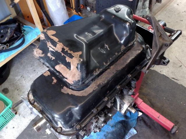
One, is that the sump is "glued" on with silicon and has to be cut away from the block. I used a snap blade knife and gradually cut the silicon away to the point where it came away. Do not force it because you could bend it and render it useless.
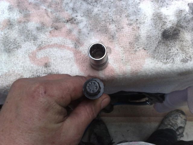
Two, is that there is a sneaky bolt for the oil cooler body hiding behind the oil filter union. You have to take the union out in order to get to the bolt. If you're unsure of what the oil cooler is, click HERE and have a look at the install guide for the location of the parts.
One thing I will stress here is that I am taking responsibility for my build only. If you follow this guide and your engine fails, that's your problem, not mine. I am confident with what I am doing and I've built many engines, but I cannot take responsibility for what you do. Use this as a guide only, and if you have access to a workshop manual, then I suggest you follow that, and not the scratchings of a lunatic such as myself who abused drugs, alcohol, and stray women until yesterday. No, the day before. No, last week. I can't remember. What was I saying?
Now, on to the rebuild!

Rebuilding A 2L-TE Engine - Toyota Surf LN130
Started by 2LV8ETR, Aug 21 2010 10:20 AM
#1

 Posted 21 August 2010 - 10:20 AM
2LV8ETR
-
- Vice President
-

- 3017 posts
Grampa Spec Cockhead
- Real Name:Allen
- LocationArmadale WA
- Car(s):RB30DET R32 Gts-t Sedan, Hilux SSR-G Surf 4x4
- Bike(s):Hyosung GT250-R, My wife...
 Back to top
#2
Posted 21 August 2010 - 10:59 AM
2LV8ETR
-
- Vice President
-
- 3017 posts
Grampa Spec Cockhead
- Real Name:Allen
- LocationArmadale WA
- Car(s):RB30DET R32 Gts-t Sedan, Hilux SSR-G Surf 4x4
- Bike(s):Hyosung GT250-R, My wife...
Step 1: Preparing the block.
If you are so inclined, send the block off to be acid dipped to save you the effort of doing things, but what's the fun in that? I always prefer to do things myself personally because I can .
.
1: Start by removing all of the gasket material on the entire block. Use a proper removal tool, not a chisel or a screwdriver. Do things the right way! Try as best as you can to avoid allowing any of the debris to fall into oil galleries. The less that gets in there, the better if you're going to do this yourself. Acid dipping will eat it away, but doing it by hand won't.
Download Full Size Image
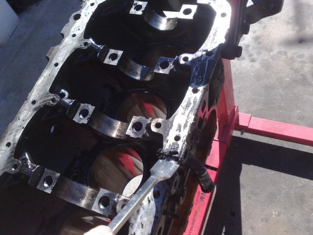
2: Clean the block down with degreaser, a selection of various scrubbing brushes, and a little elbow grease.
Download Full Size Image
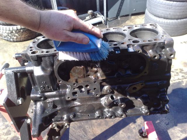
3: Use an air nozzle to remove any excess water from the surfaces and galleries. Pay careful attention to the galleries to ensure that you remove most of the water to prevent any minor rust buildup. Spin the block 90 degrees at a time and work on all of the visible surfaces. When done, do the same thing again, so do it twice. The constant rotation will work the water out.
Download Full Size Image

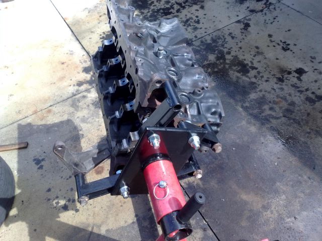
4: Spray some CRC, WD40 or some homemade brew on the bearing runners and bores to prevent surface rusting while drying the block out completely.
You can make your own brew by combining a 50%-50% ratio of light oil and turpentine. It's exactly the same stuff as the bought product.
Download Full Size Image

5: Now leave that sucker out in the sun for an hour or two to heat up and take care of any left over water residue.
Download Full Size Image
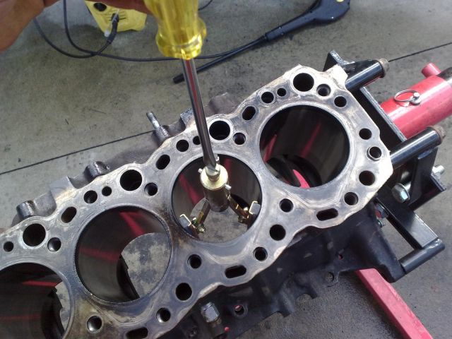
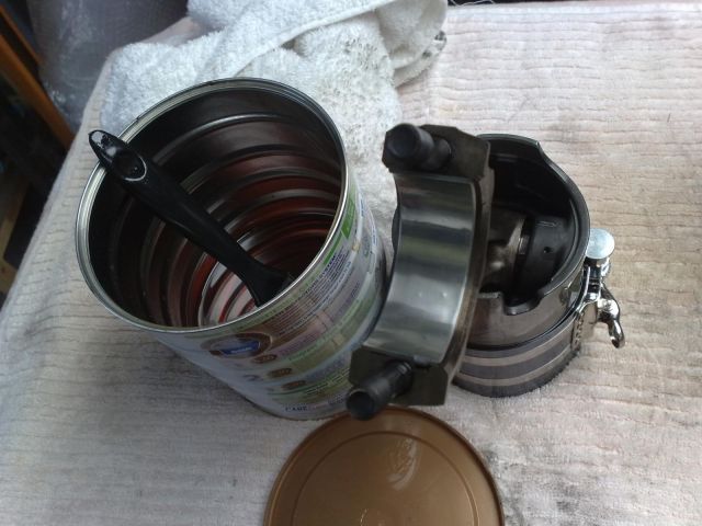
6: If you have the confidence, you can give the deridging a go. If not, send the block away again and have it done by someone who wants your money.
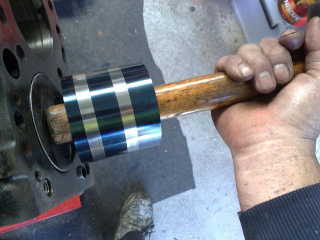
Get yourself a deridging hone if you haven't already got one. Here's mine. Take note that in the photo, the hone stones are facing backwards. In normal use, they would be pointing stretched out away from my hand.
Download Full Size Image
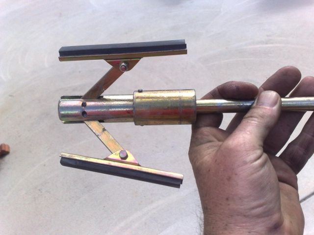
7: Set the hone in the bore and adjust it so that there's a slight amount of friction holding it in place under spring tension. It doesn't have to be tight in the bore as centrifugal force takes care of the tension on the hone stones while it's spinning. Pull it out and attach it to your drill.
Download Full Size Image
8: Apply a small amount of oil or CRC to the bore. Do not overdo it because you want the hone to grind the bore, not glide over it. The more oil you put on it, the longer you'll be trying to deridge the bore.
Download Full Size Image
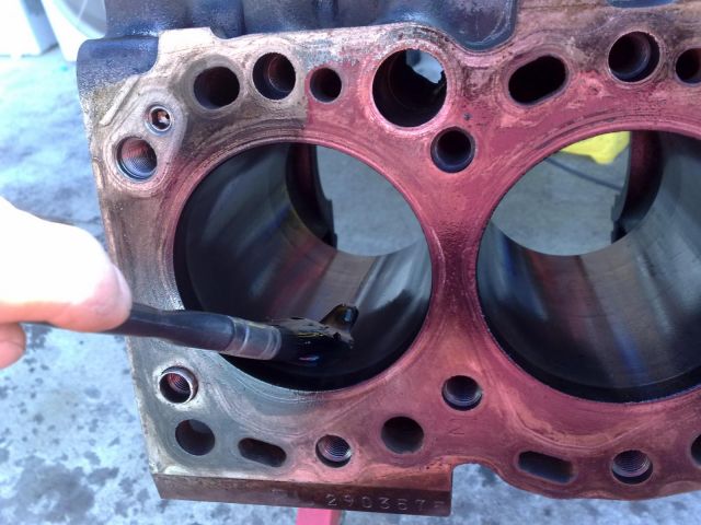
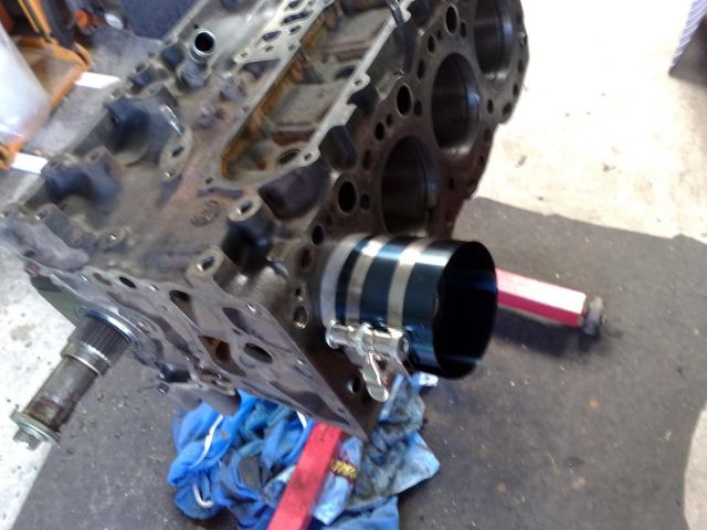
9: Spin the hone up and work it in an in and out motion paying more attention to the top of the bore where the ridge is. Stop from time to time and inspect the ridge. If it's still there, keep going until it's gone completely. When finished your bore should be smooth top to bottom. Here's a side by side comparison.
Download Full Size Image
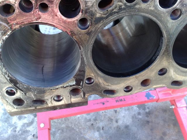
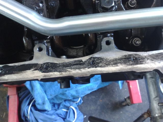
The bore on the right has not been deridged. The ridge is that black band on the right bore towards the top of the cylinder and can easily be felt.
Continue the process for every cylinder.
10: Clean the bores out with a dry and clean rag. Reapply a coat of CRC.
If you are so inclined, send the block off to be acid dipped to save you the effort of doing things, but what's the fun in that? I always prefer to do things myself personally because I can
.1: Start by removing all of the gasket material on the entire block. Use a proper removal tool, not a chisel or a screwdriver. Do things the right way! Try as best as you can to avoid allowing any of the debris to fall into oil galleries. The less that gets in there, the better if you're going to do this yourself. Acid dipping will eat it away, but doing it by hand won't.
Download Full Size Image
2: Clean the block down with degreaser, a selection of various scrubbing brushes, and a little elbow grease.
Download Full Size Image
3: Use an air nozzle to remove any excess water from the surfaces and galleries. Pay careful attention to the galleries to ensure that you remove most of the water to prevent any minor rust buildup. Spin the block 90 degrees at a time and work on all of the visible surfaces. When done, do the same thing again, so do it twice. The constant rotation will work the water out.
Download Full Size Image
4: Spray some CRC, WD40 or some homemade brew on the bearing runners and bores to prevent surface rusting while drying the block out completely.
You can make your own brew by combining a 50%-50% ratio of light oil and turpentine. It's exactly the same stuff as the bought product.
Download Full Size Image
5: Now leave that sucker out in the sun for an hour or two to heat up and take care of any left over water residue.
Download Full Size Image
6: If you have the confidence, you can give the deridging a go. If not, send the block away again and have it done by someone who wants your money.
Get yourself a deridging hone if you haven't already got one. Here's mine. Take note that in the photo, the hone stones are facing backwards. In normal use, they would be pointing stretched out away from my hand.
Download Full Size Image
7: Set the hone in the bore and adjust it so that there's a slight amount of friction holding it in place under spring tension. It doesn't have to be tight in the bore as centrifugal force takes care of the tension on the hone stones while it's spinning. Pull it out and attach it to your drill.
Download Full Size Image
8: Apply a small amount of oil or CRC to the bore. Do not overdo it because you want the hone to grind the bore, not glide over it. The more oil you put on it, the longer you'll be trying to deridge the bore.
Download Full Size Image
9: Spin the hone up and work it in an in and out motion paying more attention to the top of the bore where the ridge is. Stop from time to time and inspect the ridge. If it's still there, keep going until it's gone completely. When finished your bore should be smooth top to bottom. Here's a side by side comparison.
Download Full Size Image
The bore on the right has not been deridged. The ridge is that black band on the right bore towards the top of the cylinder and can easily be felt.
Continue the process for every cylinder.
10: Clean the bores out with a dry and clean rag. Reapply a coat of CRC.

#3
Posted 21 August 2010 - 01:26 PM
2LV8ETR
-
- Vice President
-
- 3017 posts
Grampa Spec Cockhead
- Real Name:Allen
- LocationArmadale WA
- Car(s):RB30DET R32 Gts-t Sedan, Hilux SSR-G Surf 4x4
- Bike(s):Hyosung GT250-R, My wife...
Step 2: Crank Assembly.
When I disassembled the engine, everything was still virgin on it. In other words all standard sizes were in effect with the bearing and rings. The condition of the crank was excellent so there was no need for polishing, grinding, and use of oversized components.
Now one thing to remember from this point is to ensure that your hands remain clean and free from grit. They can be oily obviously, but no grit! I always alternated rags in three steps. One being clean as a whistle, two being oily, three being dirty. I had them slung over a rail on my workbench and as the clean one got oily, I moved it further down the line discarding the dirtiest one in a pile for use as cleanup rags. I kept the air compressor on and the air nozzle hooked up to blow off every single component I picked up to remove any residual dirt, no matter how small. A tiny amount of effort to avoid a long and costly mistake.
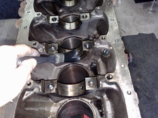
Another thing I did was kept a sealed container of diesel motor oil with a paint brush to use to lubricate surfaces. I recommend you go down the same path and keep it sealed in between use.
1: Place a light film of oil on the main bearing runners.
Download Full Size Image
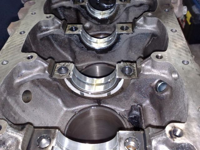
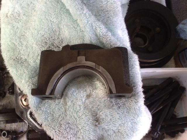
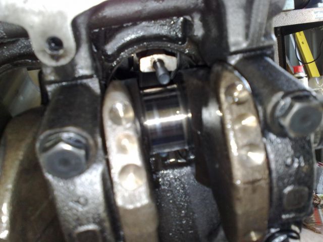
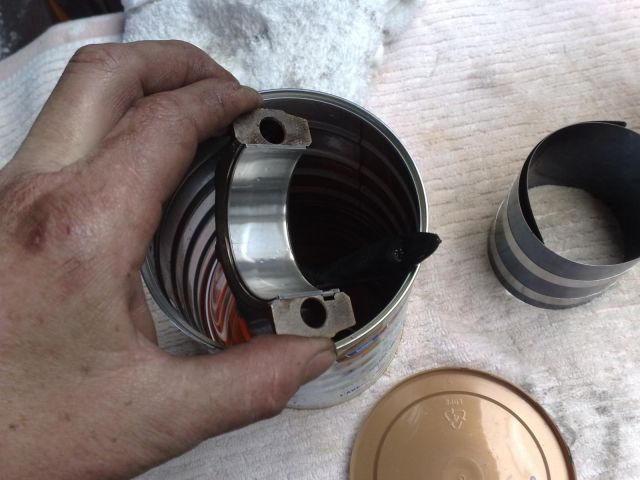
2: Install the bearings into the runners. Take note of the image below. With the mains bearings, one half of the bearing has a hole with a furrow. Make sure you line these up correctly or no oil will be able to access the crank to lubricate it. The image shows the two end runners with the bearings in place, the middle runner is without a bearing.
Download Full Size Image

Once the bearings are in place, apply a generous coating of oil.
3: Install the thrust bearings into the middle runner. You will see a groove on this runner where they are meant to be located. Take note that there is a side that has furrows, and a side that is flat. The furrows are positioned out. Another thing to remember with the thrust bearings is that one set will have tabs. The bearing being installed at this point do not have the tabs. The bearings will stay in place like this with a generous coat of oil. Also ensure that you coat both surfaces of the bearings with oil. Make sure you install them on both sides of the middle runner.
Download Full Size Image
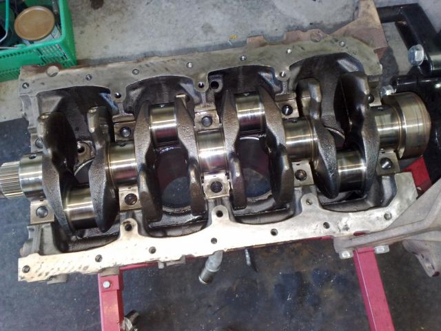
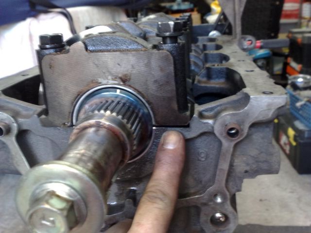
4: GENTLY lower the crank in place onto the newly installed bearings. Take note of the direction of the crank in relation to the front of the engine. The front of the crank is the part with the splined cog for the oil pump. The front of the block is the slimmest part. When lowering the crank, ensure that you do not knock the thrust bearings out of place.
Download Full Size Image
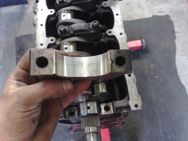
5: Apply a light film of oil onto the main bearing cap and install the bearings in the caps. Take note of the notch with which the bearing seats into. Apply a generous coat of oil onto the bearing once seated.
Download Full Size Image
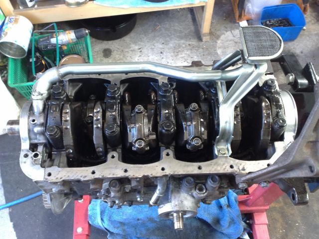
6: Place the cap onto the crank ensuring that you place them in numbered sequence. There are two numbers and an arrow marked on the cap. The arrow points to the direction of the front of the engine. The two numbers are the casting number and the cap number. The casting number is the raised number while the cap number is stamped onto the flat surface. The front of the engine is cap one, while at the rear it is cap five.
Download Full Size Image
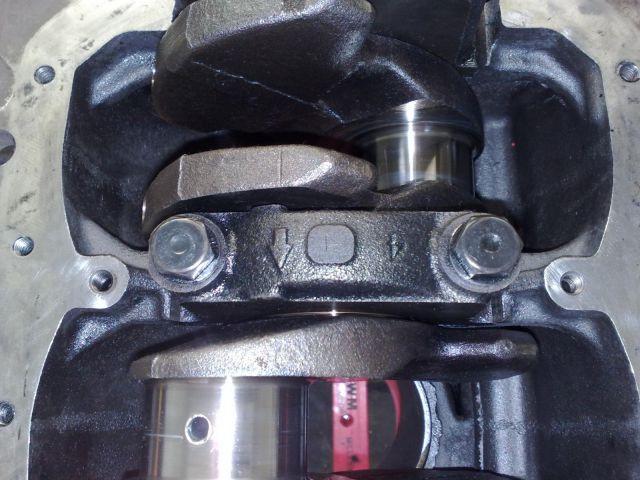
Do not install the middle cap as yet as it's covered in the next step.
The casting number is just an identifier from the factory for manufacture purposes and holds no value other than to inform the manufacturer of which die the cap was cast in. This is just in case of an event where there is a consistent moulding defect, they are able to determine which die warrants attention. If you pay attention to a lot of things that are cast or injection moulded in multiple amounts, you will find a casting number on them, even bottle tops.
7: After installing the bearing into the cap, install the thrust bearings on both sides as shown below. Again, they will stay in place with a generous coating of oil, and once in place, oil them again before placing them onto the crank. Take note also that the furrow on the bearing faces outwards.
Download Full Size Image
8: Tighten the caps down with only a slight amount of tension. Take note that the image below shows the cap at a slight angle. Nip up the high side first and then the opposite side. Remember, just a slight amount of tension for now.
Download Full Size Image
9: Now tighten down the caps using the following sequence:
Torque setting 1 - 35 Nm.
Torque setting 2 - 70 Nm.
Torque setting 3 - 103 Nm.
Start at one end of the engine and work your way to the opposite end one setting at a time. Ensure that you DO NOT skip a sequence. If you need to, use a paint pen and mark a dot on each bolt as you tighten it down per sequence. This way, before you proceed to the next setting you can count the dots on each bolt to ensure you didn't skip one. At the end you should have three dots on each bolt.
When I disassembled the engine, everything was still virgin on it. In other words all standard sizes were in effect with the bearing and rings. The condition of the crank was excellent so there was no need for polishing, grinding, and use of oversized components.
Now one thing to remember from this point is to ensure that your hands remain clean and free from grit. They can be oily obviously, but no grit! I always alternated rags in three steps. One being clean as a whistle, two being oily, three being dirty. I had them slung over a rail on my workbench and as the clean one got oily, I moved it further down the line discarding the dirtiest one in a pile for use as cleanup rags. I kept the air compressor on and the air nozzle hooked up to blow off every single component I picked up to remove any residual dirt, no matter how small. A tiny amount of effort to avoid a long and costly mistake.
Another thing I did was kept a sealed container of diesel motor oil with a paint brush to use to lubricate surfaces. I recommend you go down the same path and keep it sealed in between use.
1: Place a light film of oil on the main bearing runners.
Download Full Size Image
2: Install the bearings into the runners. Take note of the image below. With the mains bearings, one half of the bearing has a hole with a furrow. Make sure you line these up correctly or no oil will be able to access the crank to lubricate it. The image shows the two end runners with the bearings in place, the middle runner is without a bearing.
Download Full Size Image
Once the bearings are in place, apply a generous coating of oil.
3: Install the thrust bearings into the middle runner. You will see a groove on this runner where they are meant to be located. Take note that there is a side that has furrows, and a side that is flat. The furrows are positioned out. Another thing to remember with the thrust bearings is that one set will have tabs. The bearing being installed at this point do not have the tabs. The bearings will stay in place like this with a generous coat of oil. Also ensure that you coat both surfaces of the bearings with oil. Make sure you install them on both sides of the middle runner.
Download Full Size Image
4: GENTLY lower the crank in place onto the newly installed bearings. Take note of the direction of the crank in relation to the front of the engine. The front of the crank is the part with the splined cog for the oil pump. The front of the block is the slimmest part. When lowering the crank, ensure that you do not knock the thrust bearings out of place.
Download Full Size Image
5: Apply a light film of oil onto the main bearing cap and install the bearings in the caps. Take note of the notch with which the bearing seats into. Apply a generous coat of oil onto the bearing once seated.
Download Full Size Image
6: Place the cap onto the crank ensuring that you place them in numbered sequence. There are two numbers and an arrow marked on the cap. The arrow points to the direction of the front of the engine. The two numbers are the casting number and the cap number. The casting number is the raised number while the cap number is stamped onto the flat surface. The front of the engine is cap one, while at the rear it is cap five.
Download Full Size Image
Do not install the middle cap as yet as it's covered in the next step.
The casting number is just an identifier from the factory for manufacture purposes and holds no value other than to inform the manufacturer of which die the cap was cast in. This is just in case of an event where there is a consistent moulding defect, they are able to determine which die warrants attention. If you pay attention to a lot of things that are cast or injection moulded in multiple amounts, you will find a casting number on them, even bottle tops.
7: After installing the bearing into the cap, install the thrust bearings on both sides as shown below. Again, they will stay in place with a generous coating of oil, and once in place, oil them again before placing them onto the crank. Take note also that the furrow on the bearing faces outwards.
Download Full Size Image
8: Tighten the caps down with only a slight amount of tension. Take note that the image below shows the cap at a slight angle. Nip up the high side first and then the opposite side. Remember, just a slight amount of tension for now.
Download Full Size Image
9: Now tighten down the caps using the following sequence:
Torque setting 1 - 35 Nm.
Torque setting 2 - 70 Nm.
Torque setting 3 - 103 Nm.
Start at one end of the engine and work your way to the opposite end one setting at a time. Ensure that you DO NOT skip a sequence. If you need to, use a paint pen and mark a dot on each bolt as you tighten it down per sequence. This way, before you proceed to the next setting you can count the dots on each bolt to ensure you didn't skip one. At the end you should have three dots on each bolt.
#4
Posted 29 August 2010 - 11:38 PM
2LV8ETR
-
- Vice President
-
- 3017 posts
Grampa Spec Cockhead
- Real Name:Allen
- LocationArmadale WA
- Car(s):RB30DET R32 Gts-t Sedan, Hilux SSR-G Surf 4x4
- Bike(s):Hyosung GT250-R, My wife...
Step 3: Piston Inspection & Assembly.
One thing to note for the following steps is that the big end caps, and the pistons are all marked with a cylinder number. One being for the front of the engine through to four being for the rear.
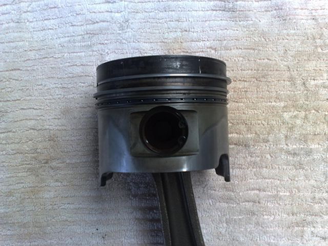
1: The first thing you should do is to inspect the pistons, rods, and gudgeon pins for wear and cracks.
Remove the rings and check behind them in the ring groove for excessive carbon buildup, which must be removed for the new rings to seat correctly. DO NOT USE A FILE!!! Use a thin brass brush or something similar to clean the groove. If you use a file, you could damage the ring lands and cause more harm than good.
Clean the pistons up and look for cracks and scoring. Same again, don't use anything that could damage the piston. A brass wire brush will do the trick.
Check to see if there is any slop in the gudgeon pins. Don't count the side by side sliding of the rod on the pin as slop, as this is normal. What you need to be looking for here is slop between the pin and the rod surface.
Check the rod bearing (known as the big end) carrier for scoring. If the rod itself was knackered, you'll know that by it being the shape of a banana, and your bore's being rough, so don't panic too much here with the rods.
Download Full Size Image
If anything here is cactus, replace it. My gear was all good so I have no images for you to go by if you need to disassemble and replace any of the parts, but if you are capable of going this far, then you can nut it out when you take the assembly apart. It's just held in by a circlip.
If you really need help here, ask a friend, or a friendly mechanic who would be happy to show you quickly how to do what you need done. At the point of writing this, the engine has been fully reassembled, installed, and is running, so I'm not going to rip it all out to show you how it's done.
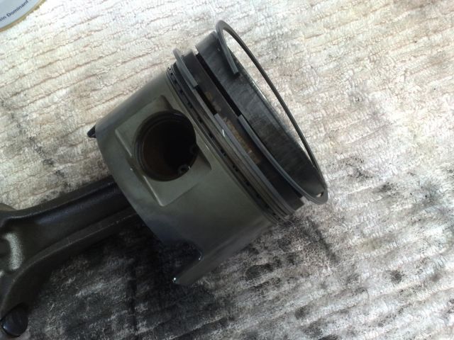
2: Slip the oil ring over the piston from the bottom until it seats into the groove. By doing this, you don't have to try and clear the first two compression ring grooves. The oil ring is easily identifiable from the compression rings as it has a spring looking ring wound on the inside. The two compression rings are flat.
Download Full Size Image
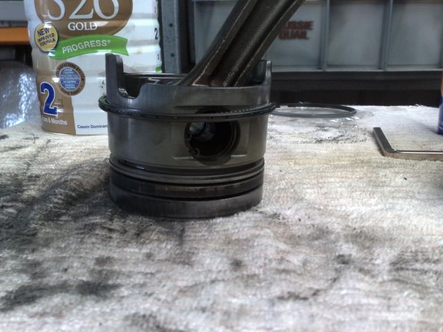
3: Have a close look at the image below. It shows the two compression rings on top of each other. The first (top) compression ring is the thinner of the two. The second (middle) compression ring has the weight problem, so it's fatter, or should we be politically correct and say horizontally challenged.
Download Full Size Image
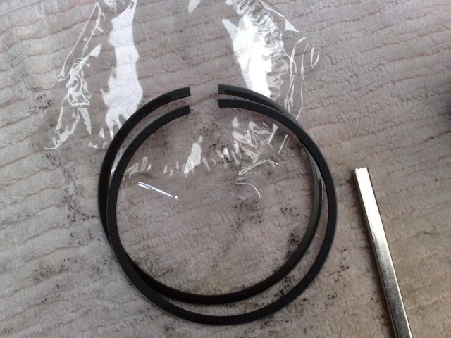
Don't get these two mixed up in the next steps.
4: Install the second ring before the first, that's the fat boy. These things are brittle so take care not to overstretch them when installing or else they'll shatter into several pieces. Slip one end into the second ring groove, leaving the other end on top of the piston.
Download Full Size Image
Slide the opposite end down to the second groove. You'll need to pull a little on this away from the piston to avoid dragging the end onto the surface and score it in the process. Only a little tension is needed, too much and she'll shatter.
Download Full Size Image

Again with a little tension only, pull the rear of the ring up and over into the second groove. At this point, it should be completely seated in the groove.
Download Full Size Image
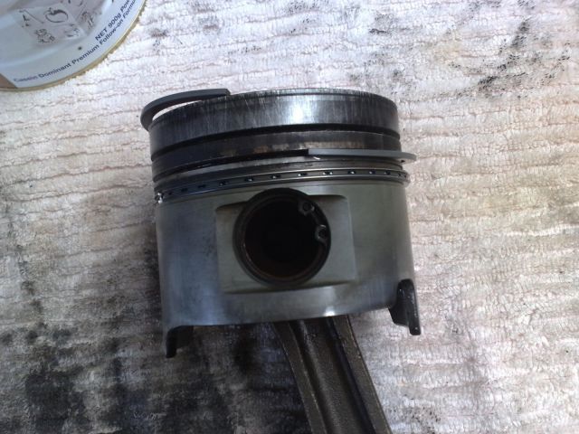
5: Now we tackle the first compression ring. As above, slip one end into the first ring groove.
Download Full Size Image
Slowly work the ring around until the opposite end slots into the groove. Again, slight tension is needed to pull it away from the piston to avoid scoring, and again, overdoing it will shatter the ring.
Download Full Size Image

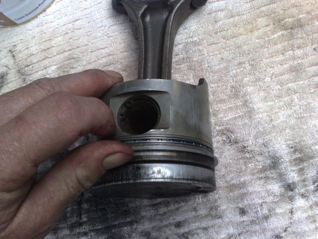
6: The following image shows a marking on the piston which indicates the direction for the front of the engine. When installing the piston in the steps below, make sure that this mark points towards the front.
Download Full Size Image

7: Lubricate the inside of the ring compressor with some oil or WD40 and slip your ring compressor over the top of the rings and tighten the compressor as much as you can. Leave the lower part of the piston uncovered so it can be slotted into the bore.
Download Full Size Image

8: Brush some oil on the big end carrier. Place the big end bearing on the rod and again brush some oil onto the bearing once in place. Also note the notch for position of the bearing.
Download Full Size Image
9: Start at piston number one, and turn the crank so that the apex is at the top of the block. Place the piston in the bore taking note to ensure that the identification mark shown in step 6 is facing the front of the engine. Make sure that rod is aligned with the crank by looking from the bottom of the engine, and through the cylinder.
Download Full Size Image
Using the wooden end of a hammer or mallet, slowly knock the piston in with one hand, and reach around into the block holding the end of the rod to make sure that the big end is aligned with the crank. The last thing you want to do here is score the crank with the rod bolts. The bolts at the end of the rod need to straddle the crank. Support the rod while tapping lightly on the top of the piston at the same time. Make sure that while you tap the piston in, that you keep an eye on the compressor to ensure that it maintains contact with the top of the block, and that the rings don't fall out before entering the top of the cylinder.
Download Full Size Image

The image below shows the rod slightly out of alignment with the crank. This is for reference only.
Download Full Size Image
Once the piston has been successfully seated in the bore, the compressor will fall away.
Download Full Size Image
10: Brush some oil on the big end cap. Place the big end bearing into the cap and again brush some oil onto the bearing once in place. Also note the notch for position of the bearing.
Download Full Size Image
Take note of the tab in the image below. It indicates the direction to the front of the engine for installation in step 11.
Download Full Size Image

Another thing to be aware of is that the nuts used for the big end caps require a double hex socket as shown below.
Download Full Size Image

Before placing the cap, make sure that the big end bearing is still located on the end of the rod, and not on the floor. Place the cap on the end of the rod making sure that the tab is facing the front of the engine, and pre-tighten the nut on the big end cap by hand only. This will allow for easier torquing in step 11.
Download Full Size Image
11: Torque the cap nuts to 54 Nm. Again if you need to, mark each nut with a paint pen dot once you torque it up to ensure that you have done every single one.
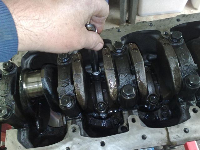
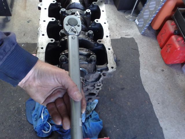
12: Now give each nut a 90 degree turn. The first image below shows the position of the torque wrench before the 90 degree turn. The second image shows the position of the wrench AFTER the 90 degree turn.
Pre 90 Degree:
Download Full Size Image
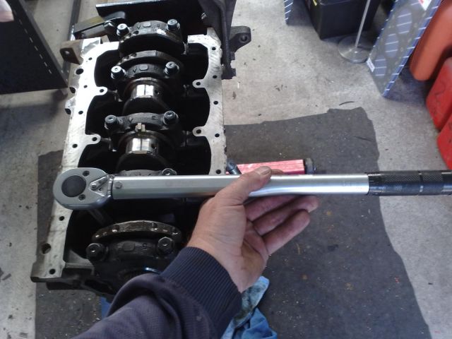
After 90 Degree:
Download Full Size Image
Repeat this for every nut ONCE only.
The big end is complete.
One thing to note for the following steps is that the big end caps, and the pistons are all marked with a cylinder number. One being for the front of the engine through to four being for the rear.
1: The first thing you should do is to inspect the pistons, rods, and gudgeon pins for wear and cracks.
Remove the rings and check behind them in the ring groove for excessive carbon buildup, which must be removed for the new rings to seat correctly. DO NOT USE A FILE!!! Use a thin brass brush or something similar to clean the groove. If you use a file, you could damage the ring lands and cause more harm than good.
Clean the pistons up and look for cracks and scoring. Same again, don't use anything that could damage the piston. A brass wire brush will do the trick.
Check to see if there is any slop in the gudgeon pins. Don't count the side by side sliding of the rod on the pin as slop, as this is normal. What you need to be looking for here is slop between the pin and the rod surface.
Check the rod bearing (known as the big end) carrier for scoring. If the rod itself was knackered, you'll know that by it being the shape of a banana, and your bore's being rough, so don't panic too much here with the rods.
Download Full Size Image
If anything here is cactus, replace it. My gear was all good so I have no images for you to go by if you need to disassemble and replace any of the parts, but if you are capable of going this far, then you can nut it out when you take the assembly apart. It's just held in by a circlip.
If you really need help here, ask a friend, or a friendly mechanic who would be happy to show you quickly how to do what you need done. At the point of writing this, the engine has been fully reassembled, installed, and is running, so I'm not going to rip it all out to show you how it's done.
2: Slip the oil ring over the piston from the bottom until it seats into the groove. By doing this, you don't have to try and clear the first two compression ring grooves. The oil ring is easily identifiable from the compression rings as it has a spring looking ring wound on the inside. The two compression rings are flat.
Download Full Size Image
3: Have a close look at the image below. It shows the two compression rings on top of each other. The first (top) compression ring is the thinner of the two. The second (middle) compression ring has the weight problem, so it's fatter, or should we be politically correct and say horizontally challenged.
Download Full Size Image
Don't get these two mixed up in the next steps.
4: Install the second ring before the first, that's the fat boy. These things are brittle so take care not to overstretch them when installing or else they'll shatter into several pieces. Slip one end into the second ring groove, leaving the other end on top of the piston.
Download Full Size Image
Slide the opposite end down to the second groove. You'll need to pull a little on this away from the piston to avoid dragging the end onto the surface and score it in the process. Only a little tension is needed, too much and she'll shatter.
Download Full Size Image
Again with a little tension only, pull the rear of the ring up and over into the second groove. At this point, it should be completely seated in the groove.
Download Full Size Image
5: Now we tackle the first compression ring. As above, slip one end into the first ring groove.
Download Full Size Image
Slowly work the ring around until the opposite end slots into the groove. Again, slight tension is needed to pull it away from the piston to avoid scoring, and again, overdoing it will shatter the ring.
Download Full Size Image
6: The following image shows a marking on the piston which indicates the direction for the front of the engine. When installing the piston in the steps below, make sure that this mark points towards the front.
Download Full Size Image
7: Lubricate the inside of the ring compressor with some oil or WD40 and slip your ring compressor over the top of the rings and tighten the compressor as much as you can. Leave the lower part of the piston uncovered so it can be slotted into the bore.
Download Full Size Image
8: Brush some oil on the big end carrier. Place the big end bearing on the rod and again brush some oil onto the bearing once in place. Also note the notch for position of the bearing.
Download Full Size Image
9: Start at piston number one, and turn the crank so that the apex is at the top of the block. Place the piston in the bore taking note to ensure that the identification mark shown in step 6 is facing the front of the engine. Make sure that rod is aligned with the crank by looking from the bottom of the engine, and through the cylinder.
Download Full Size Image
Using the wooden end of a hammer or mallet, slowly knock the piston in with one hand, and reach around into the block holding the end of the rod to make sure that the big end is aligned with the crank. The last thing you want to do here is score the crank with the rod bolts. The bolts at the end of the rod need to straddle the crank. Support the rod while tapping lightly on the top of the piston at the same time. Make sure that while you tap the piston in, that you keep an eye on the compressor to ensure that it maintains contact with the top of the block, and that the rings don't fall out before entering the top of the cylinder.
Download Full Size Image
The image below shows the rod slightly out of alignment with the crank. This is for reference only.
Download Full Size Image
Once the piston has been successfully seated in the bore, the compressor will fall away.
Download Full Size Image
10: Brush some oil on the big end cap. Place the big end bearing into the cap and again brush some oil onto the bearing once in place. Also note the notch for position of the bearing.
Download Full Size Image
Take note of the tab in the image below. It indicates the direction to the front of the engine for installation in step 11.
Download Full Size Image
Another thing to be aware of is that the nuts used for the big end caps require a double hex socket as shown below.
Download Full Size Image
Before placing the cap, make sure that the big end bearing is still located on the end of the rod, and not on the floor. Place the cap on the end of the rod making sure that the tab is facing the front of the engine, and pre-tighten the nut on the big end cap by hand only. This will allow for easier torquing in step 11.
Download Full Size Image
11: Torque the cap nuts to 54 Nm. Again if you need to, mark each nut with a paint pen dot once you torque it up to ensure that you have done every single one.
12: Now give each nut a 90 degree turn. The first image below shows the position of the torque wrench before the 90 degree turn. The second image shows the position of the wrench AFTER the 90 degree turn.
Pre 90 Degree:
Download Full Size Image
After 90 Degree:
Download Full Size Image
Repeat this for every nut ONCE only.
The big end is complete.
#5
Posted 09 September 2010 - 08:49 PM
2LV8ETR
-
- Vice President
-
- 3017 posts
Grampa Spec Cockhead
- Real Name:Allen
- LocationArmadale WA
- Car(s):RB30DET R32 Gts-t Sedan, Hilux SSR-G Surf 4x4
- Bike(s):Hyosung GT250-R, My wife...
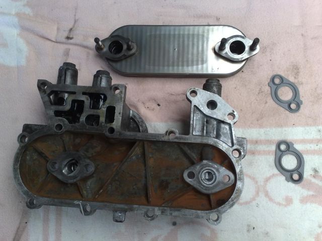
Step 4: Oil Cooler Assembly
1: Below is an image showing the oil cooler, the gaskets, and the housing.
Download Full Size Image
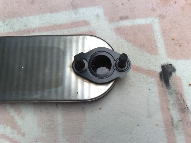
2: Place the gaskets on both of the oil cooler entry/exit points.
Download Full Size Image
3: Position the oil cooler into the housing and tighten the 4 nuts to a torque setting of 14 Nm.
Download Full Size Image

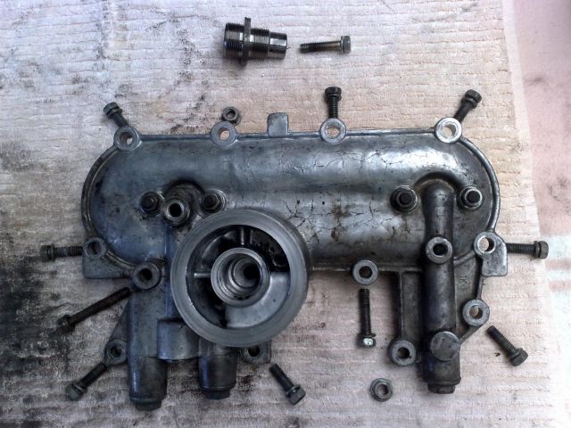
4: What I have done in the image below is show the bolts used for the various locations on the housing. The tip of the bolts are pointing to the corresponding holes, while the 2 nuts are positioned next to the holes in the housing. At the very top are the oil filter union, and the bolt that is located behind it.
Position the oil cooler housing gasket onto the block and place the housing onto the studs.
Now put all of the bolts and nuts into their respective locations as shown above and tighten the bolts to 19 Nm, and the nuts to 21 Nm.
A couple of these bolts will need to be backed out later, but put them in for now to better seal the housing.
Download Full Size Image
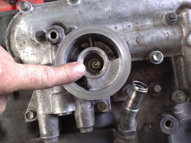
5: Shown below is the location of the "sneaky bastard" bolt behind the oil filter union.
Download Full Size Image
6: Apply a SMALL amount of Loctite to a couple of threads of the oil filter union, screw into place, and tighten to 42 Nm. Note that the short threaded end goes into the oil cooler housing.
Download Full Size Image
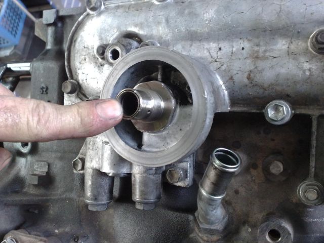
Use a large socket to tighten up the oil filter union, or donate a couple of hundred bucks to Toyota for SST 09326-20011.
1: Below is an image showing the oil cooler, the gaskets, and the housing.
Download Full Size Image
2: Place the gaskets on both of the oil cooler entry/exit points.
Download Full Size Image
3: Position the oil cooler into the housing and tighten the 4 nuts to a torque setting of 14 Nm.
Download Full Size Image
4: What I have done in the image below is show the bolts used for the various locations on the housing. The tip of the bolts are pointing to the corresponding holes, while the 2 nuts are positioned next to the holes in the housing. At the very top are the oil filter union, and the bolt that is located behind it.
Position the oil cooler housing gasket onto the block and place the housing onto the studs.
Now put all of the bolts and nuts into their respective locations as shown above and tighten the bolts to 19 Nm, and the nuts to 21 Nm.
A couple of these bolts will need to be backed out later, but put them in for now to better seal the housing.
Download Full Size Image
5: Shown below is the location of the "sneaky bastard" bolt behind the oil filter union.
Download Full Size Image
6: Apply a SMALL amount of Loctite to a couple of threads of the oil filter union, screw into place, and tighten to 42 Nm. Note that the short threaded end goes into the oil cooler housing.
Download Full Size Image
Use a large socket to tighten up the oil filter union, or donate a couple of hundred bucks to Toyota for SST 09326-20011.
#6
Posted 09 September 2010 - 09:12 PM
2LV8ETR
-
- Vice President
-
- 3017 posts
Grampa Spec Cockhead
- Real Name:Allen
- LocationArmadale WA
- Car(s):RB30DET R32 Gts-t Sedan, Hilux SSR-G Surf 4x4
- Bike(s):Hyosung GT250-R, My wife...
Step 5: Crank Angle Sensor
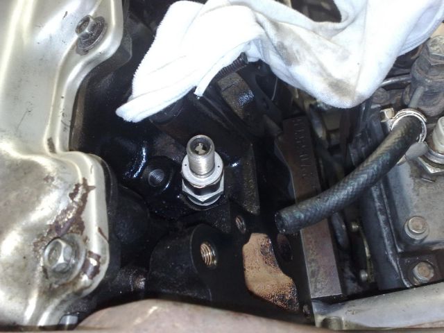
This is an easy step but an important one. Just be aware of the O-ring around the sensor and be sure that you don't foul it after inserting it.
What I did here was place a small amount of oil around the O-ring and also around the entry hole. I then inserted the sensor using a twisting motion as I slowly pushed it in.
Once it's in place, bolt it in.
The sensor is located next to the dipstick.
Download Full Size Image
#7
Posted 09 September 2010 - 09:27 PM
2LV8ETR
-
- Vice President
-
- 3017 posts
Grampa Spec Cockhead
- Real Name:Allen
- LocationArmadale WA
- Car(s):RB30DET R32 Gts-t Sedan, Hilux SSR-G Surf 4x4
- Bike(s):Hyosung GT250-R, My wife...
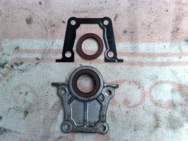
Step 6: Rear Main Seal Assembly
1: The main seal housing and gasket.
Download Full Size Image
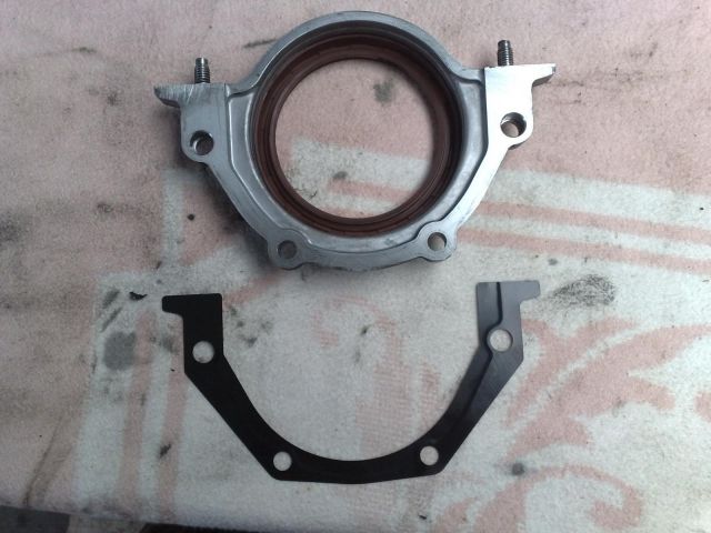
2: Press out the old seal and clean the housing. Once cleaned press the new seal into place.
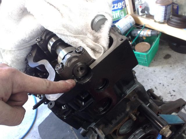
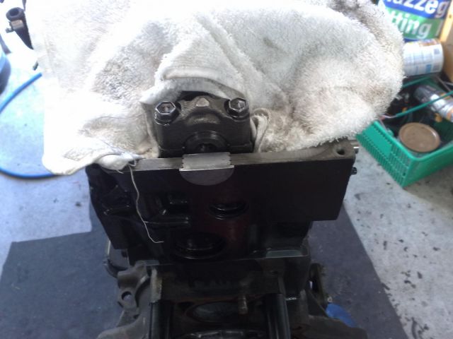
3: Place the two top bolts into the housing and position the gasket onto the bolts. This is assuming that you have the engine upside-down on the stand and the bolts I'm referring to are the two nearest the sump studs.
4: This is where it gets a little tricky because if you're like me, the engine is on a stand and there is very little room to position the housing and tighten the bolts up. It's doable, but it is a little tricky. If your wife has small hands, drag her away from the kitchen for a couple of minutes to screw the bolts in for you. Once done, tell her to get you a beer, and then dismiss her back to her duties. After she's left, have a chuckle and tighten all four bolts up.
Download Full Size Image

1: The main seal housing and gasket.
Download Full Size Image
2: Press out the old seal and clean the housing. Once cleaned press the new seal into place.
3: Place the two top bolts into the housing and position the gasket onto the bolts. This is assuming that you have the engine upside-down on the stand and the bolts I'm referring to are the two nearest the sump studs.
4: This is where it gets a little tricky because if you're like me, the engine is on a stand and there is very little room to position the housing and tighten the bolts up. It's doable, but it is a little tricky. If your wife has small hands, drag her away from the kitchen for a couple of minutes to screw the bolts in for you. Once done, tell her to get you a beer, and then dismiss her back to her duties. After she's left, have a chuckle and tighten all four bolts up.
Download Full Size Image
#8
Posted 09 September 2010 - 09:42 PM
2LV8ETR
-
- Vice President
-
- 3017 posts
Grampa Spec Cockhead
- Real Name:Allen
- LocationArmadale WA
- Car(s):RB30DET R32 Gts-t Sedan, Hilux SSR-G Surf 4x4
- Bike(s):Hyosung GT250-R, My wife...
Step 7: Front Cover Assembly
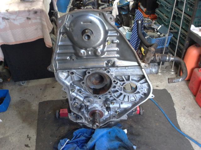
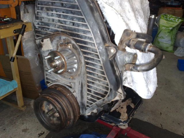
1: This is essentially the lower backing plate for the timing cover and also incorporates the oil pump.
The image below shows the five bolts we'll be dealing with in this first part of the assembly. The bolt ends again point to the holes we're using for this step.
The hole at the bottom is positioned over the crank and is the oil pump drive. The shaped opening above it is where the water pump sits, and the hole to the right is for the injector pump.
Download Full Size Image

2: The first step is to press out the old oil pump seal and clean the cover up. Don't go immersing it in water as you could contaminate the oil pump. I used a bit of degreaser on a rag and a scrubbing brush. Once it's clean enough wipe it down with a dry rag to remove the degreaser.
Once cleaned press the new seal into place.
3: Position the gasket onto the block and position the oil pump gear over the crank. You may need to move it around a little to engage the pump gear onto the crank gear.
Once it's slipped over the crank, place the five bolts into the holes on the cover shown above and tighten them up.
Download Full Size Image
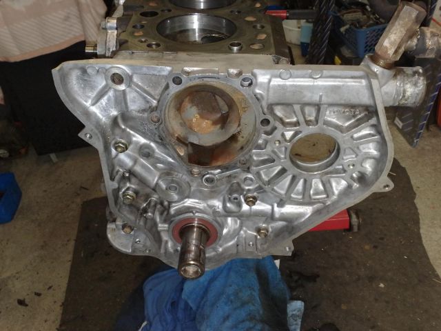
Note that I have not removed the heater and turbo return line. If you have removed these, then you can put them on at the end of this step, or after the engine is installed.
1: This is essentially the lower backing plate for the timing cover and also incorporates the oil pump.
The image below shows the five bolts we'll be dealing with in this first part of the assembly. The bolt ends again point to the holes we're using for this step.
The hole at the bottom is positioned over the crank and is the oil pump drive. The shaped opening above it is where the water pump sits, and the hole to the right is for the injector pump.
Download Full Size Image
2: The first step is to press out the old oil pump seal and clean the cover up. Don't go immersing it in water as you could contaminate the oil pump. I used a bit of degreaser on a rag and a scrubbing brush. Once it's clean enough wipe it down with a dry rag to remove the degreaser.
Once cleaned press the new seal into place.
3: Position the gasket onto the block and position the oil pump gear over the crank. You may need to move it around a little to engage the pump gear onto the crank gear.
Once it's slipped over the crank, place the five bolts into the holes on the cover shown above and tighten them up.
Download Full Size Image
Note that I have not removed the heater and turbo return line. If you have removed these, then you can put them on at the end of this step, or after the engine is installed.
#9
Posted 09 September 2010 - 10:06 PM
2LV8ETR
-
- Vice President
-
- 3017 posts
Grampa Spec Cockhead
- Real Name:Allen
- LocationArmadale WA
- Car(s):RB30DET R32 Gts-t Sedan, Hilux SSR-G Surf 4x4
- Bike(s):Hyosung GT250-R, My wife...
Step 8: Sump Assembly
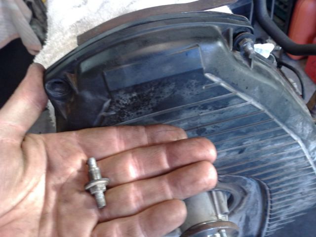
1: Shown in the image below is the sump pickup and parts.
Download Full Size Image
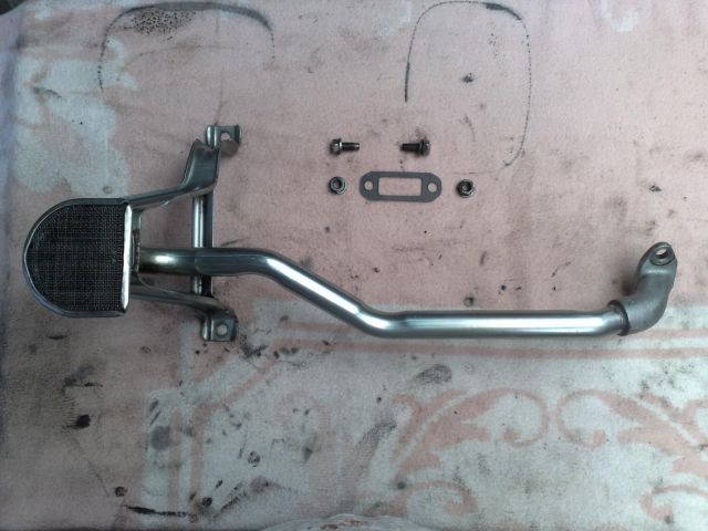
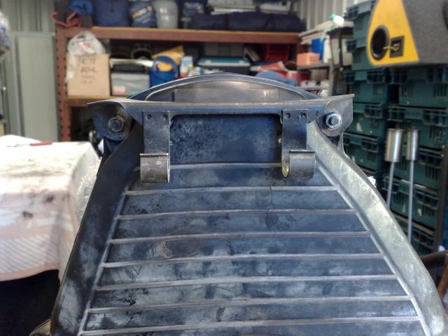
2: Place the two bolts into the end of the pickup that's away from the screened end. Place the gasket over the bolts, locate them into position onto the pickup inlet and tighten them down.
Locate the two bracket bolts and tighten them down as well.
Download Full Size Image
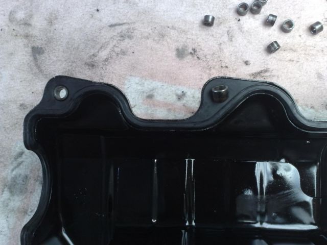
3: Place a silicone bead onto the sump. Don't be stingy. Once you've laid the bead, use your finger to even it out around all of the mating surface. Ideally the thickness should be about 1mm.
Remove any excess from the inner side of the surface.
Download Full Size Image

4: Place a very light silicone bead onto the block. Once you've laid the bead, use your finger to even it out around the mating surface. This should only be a thin film.
Remove any excess from the inner side of the surface.
Download Full Size Image
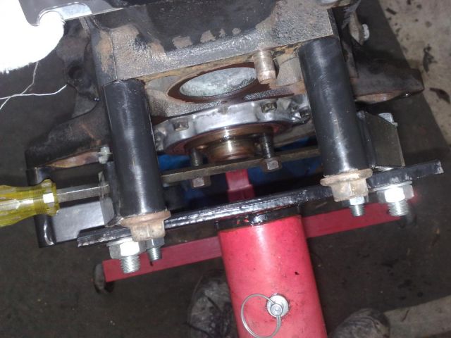
5: Position the sump into place and tighten it down with the bolts. There will be two nuts which are located on the rear main seal housing.
Download Full Size Image
6: Smooth out the remaining silicone between the sump and the block. There is no need to remove it as it is beneficial to have it there for extra sealing.
1: Shown in the image below is the sump pickup and parts.
Download Full Size Image
2: Place the two bolts into the end of the pickup that's away from the screened end. Place the gasket over the bolts, locate them into position onto the pickup inlet and tighten them down.
Locate the two bracket bolts and tighten them down as well.
Download Full Size Image
3: Place a silicone bead onto the sump. Don't be stingy. Once you've laid the bead, use your finger to even it out around all of the mating surface. Ideally the thickness should be about 1mm.
Remove any excess from the inner side of the surface.
Download Full Size Image
4: Place a very light silicone bead onto the block. Once you've laid the bead, use your finger to even it out around the mating surface. This should only be a thin film.
Remove any excess from the inner side of the surface.
Download Full Size Image
5: Position the sump into place and tighten it down with the bolts. There will be two nuts which are located on the rear main seal housing.
Download Full Size Image
6: Smooth out the remaining silicone between the sump and the block. There is no need to remove it as it is beneficial to have it there for extra sealing.
#10
Posted 13 September 2010 - 10:02 PM
2LV8ETR
-
- Vice President
-
- 3017 posts
Grampa Spec Cockhead
- Real Name:Allen
- LocationArmadale WA
- Car(s):RB30DET R32 Gts-t Sedan, Hilux SSR-G Surf 4x4
- Bike(s):Hyosung GT250-R, My wife...
Step 9: Head Assembly
First, some familiarisation of the various parts that we'll be dealing with in this step.
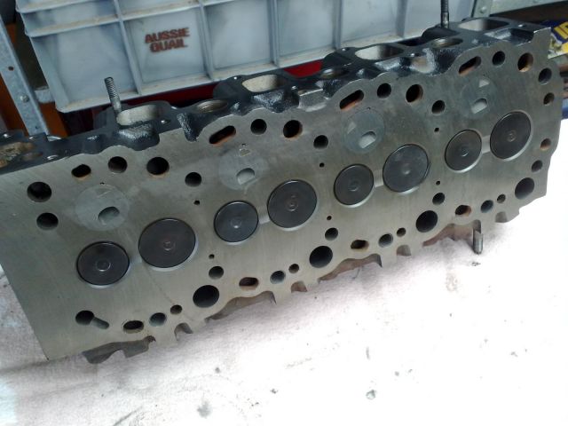
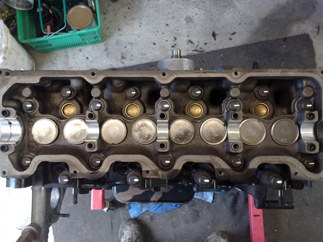
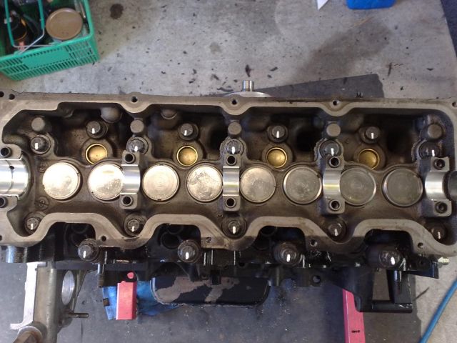
1: The image below shows the head, cam, and cam caps.
Download Full Size Image
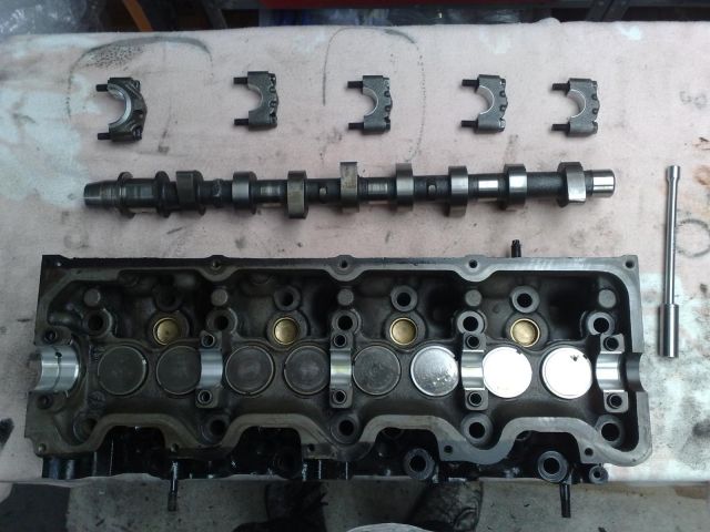
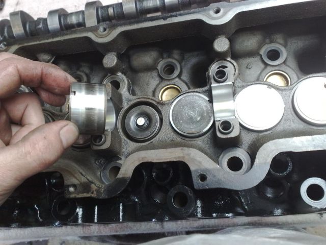
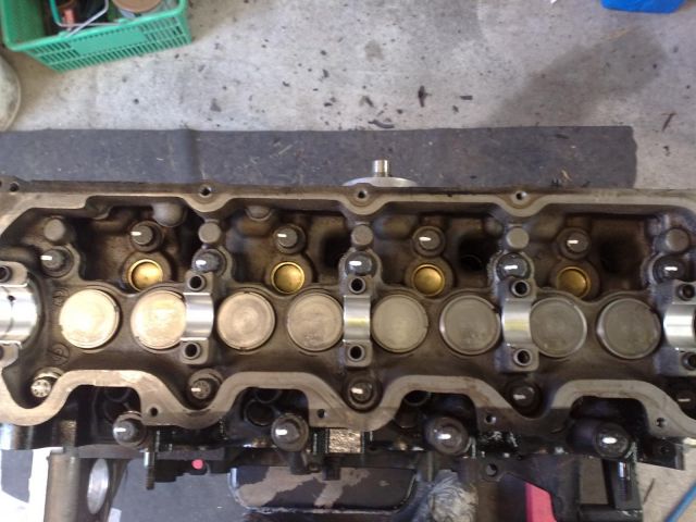
2: The image below shows the lifter caps that the cam rides for operation of the valves.
Download Full Size Image
3: I sent my head away to be tested and decked. I don't have the equipment to do this so it's one of the very few stages that I have to entrust to someone else.
What happens in this process is the machinist grinds down the side that faces the block so it creates an even surface for mating between the block, the head gasket, and the head itself. If the head is slightly warped at all, this will fix that issue.
While it was away they replaced some valve guides, seals, shimmed the valves and supplied the cam bearings.
The first thing to do is to place the cam bearing into their respective locations. Use the same principles as when you did the main, and big end bearings. Note that the two odd bearings are the thrust bearings and these go on the very first runners. You will see this in the first image above.
Download Full Size Image
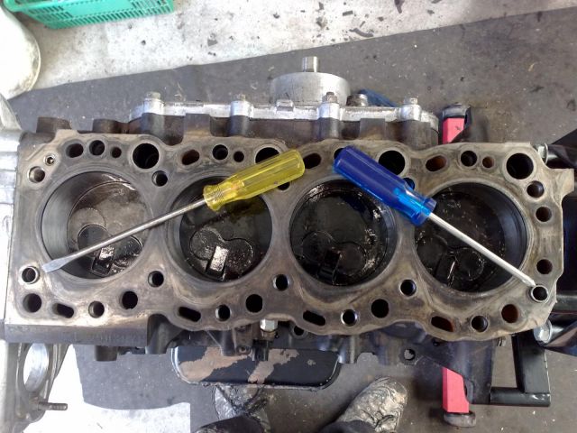
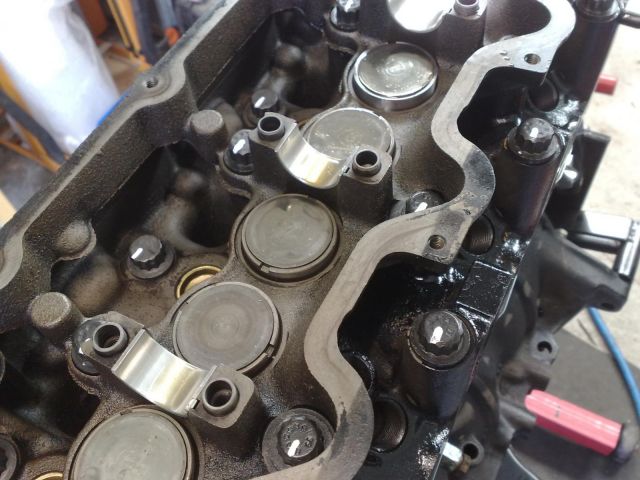
4: The image below shows the location of the dowels for proper alignment of the head to the block. The tips of the screwdrivers shows where they are.
Download Full Size Image
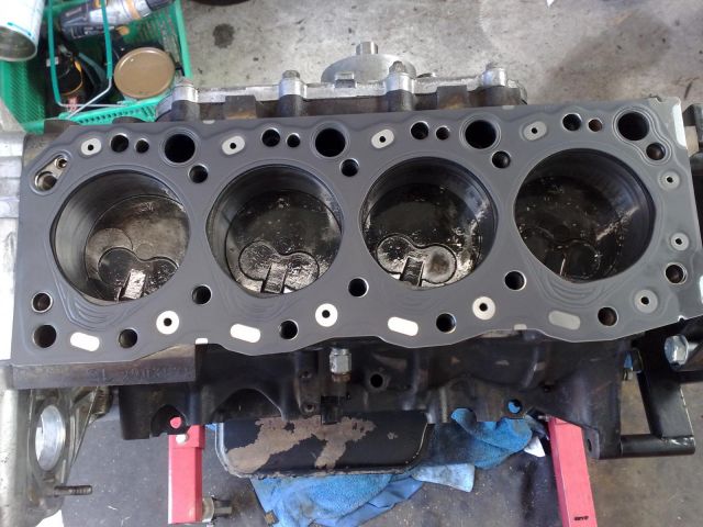
5: Place the head gasket on the block. It will only go on one way correctly so there's little chance of messing this up. I went for a 1.65mm gasket to compensate for the piston protrusion.
If you don't purchase the correct size gasket, you may end up putting a valve through the piston. In order to check for the correct size gasket, use a dial indicator to measure the amount of piston protrusion from the block. With that measurement, select the following size:
0.68mm-0.77mm protrusion - 1.40mm-1.50mm gasket
0.78mm-0.87mm protrusion - 1.50mm-1.60mm gasket
0.88mm-0.97mm protrusion - 1.60mm-1.70mm gasket
Download Full Size Image
6: Very gently, place the head on the block and align the dowels. The head will have very little movement once it drops into the dowels. If it slides all over the block, then you've got it wrong.
Download Full Size Image

7: As with the big end caps, the head bolts use a 14mm double hex socket.
Download Full Size Image
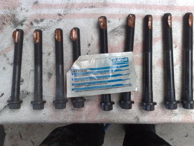
8: Grease the head bolts with the copper grease that comes with the new head bolts. You just need a little on one section of the thread to do the job. Also be aware that there are 4 shorter bolts.
If you look at the top of the head, you will see four core plugs. The four short bolts go in the holes next to these plugs.
Download Full Size Image
9: Torque the head down to 78 Nm. Use the following sequence:
11 3 5 13
17 9 1 7 15
<F
16 8 2 10 18
14 6 4 12
<F denotes the front of the engine. Usually head gaskets come with a sequence chart on the packaging. The one I used above differed slightly from what was printed on the gasket packaging, but it was close enough to not be an issue if you chose to use either.
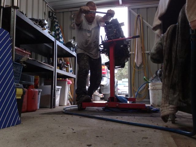
78 Nm is a fair amount of force and the engine stand kept wanting to move when I was doing the bolts up. I overcame this by placing one foot on the stand and pulled the wrench towards me.
Download Full Size Image
10: Now mark the rear of the bolt head with a paint pen. The reason for this is because the next two tightening sequences are in 90 degree increments. It serves the purpose of visually ensuring that each bolt is tightened in between, and at the end of the next two stages.
Download Full Size Image
11: Using the same sequence above, tighten the bolts 90 degrees. At the end, they should all be facing the same way as in the image below.
Download Full Size Image
12: Again, using the same sequence, tighten the bolts a further 90 degrees. When the whole thing is over, pick your bowels up off the floor and have a look at the bolts. The marks should all now be facing the front of the engine.
Download Full Size Image
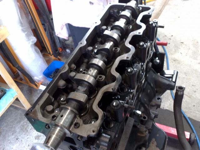
13: Lubricate all of the cam bearings.
Download Full Size Image
14: Very gently, lay the cam in place onto the bearings with the cam gear keyway facing upwards. The keyway is located on the front of the cam and is basically a groove in the conical surface. With the keyway facing upwards, the cam is close to TDC.
Take note that the cam will not lay flat on the bearings as the lobes facing the valves will prevent this from occurring.
Download Full Size Image
Now place the caps over the cam using the respective numbers, note the direction of forward facing, and tighten them by hand only at first. Leave the number one cap with the thrust bearing out at first.
Tighten down the cap bolts a little each time from front to back, then repeat the process a little at a time until the bolts are just tight. This will slowly bring the lobes onto the lifters and push the respective valves down until the cam is seated.
Now you can put the cap with the thrust bearings into place and tighten down, again until just tight. The reason for leaving this until last is so that it doesn't twist the thrust bearings due to the angle of the cam before tightening down.
Torque the cap bolts to 52 Nm.
15: The image below shows the front cam seal and gasket. As with the previous stages, press out the old cam seal, clean the housing up, and press the new cam seal into place.
Download Full Size Image
16: Place a little oil on the cam seal and slip into place. Tighten the four bolts.
Download Full Size Image

17: The image below shows the rear cam seal and its location.
Download Full Size Image
18: Place a film of silicone onto the curved side of the seal, making sure that the grooves are completely filled. Position the seal into place and ensure that the flat ends on top line up with each side of the valley.
Download Full Size Image
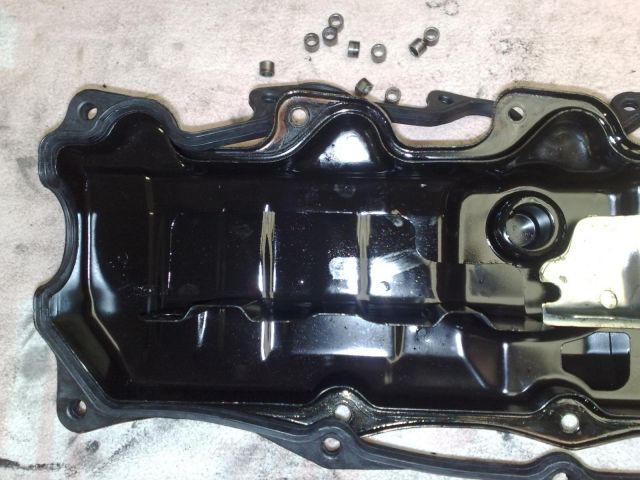
19: Remove the old rocker cover seal, but retain the dowels.
Replace the new seal starting at the front. Start by putting the curved section in first and follow up with each side to the bolt hole. What ever you do, DO NOT use a screwdriver or something stupid like that to press it into place.
Continue along each side one bolt hole at a time, alternating sides as you go until you reach the opposite end.
Download Full Size Image
20: Press the dowels into the gasket. In the image below, the left side is in and positioned, while the right one is just sitting there for reference. Don't try to push it in this way.
You'll need strong fingers to get these dowels in. Years of masturbation have blessed me with strong hands. If you have too much difficulty, use a pair of adjustable pliers and squeeze them into place.
Download Full Size Image
21: Position the rocker cover in place and tighten the bolts to 4.9 Nm.
First, some familiarisation of the various parts that we'll be dealing with in this step.
1: The image below shows the head, cam, and cam caps.
Download Full Size Image
2: The image below shows the lifter caps that the cam rides for operation of the valves.
Download Full Size Image
3: I sent my head away to be tested and decked. I don't have the equipment to do this so it's one of the very few stages that I have to entrust to someone else.
What happens in this process is the machinist grinds down the side that faces the block so it creates an even surface for mating between the block, the head gasket, and the head itself. If the head is slightly warped at all, this will fix that issue.
While it was away they replaced some valve guides, seals, shimmed the valves and supplied the cam bearings.
The first thing to do is to place the cam bearing into their respective locations. Use the same principles as when you did the main, and big end bearings. Note that the two odd bearings are the thrust bearings and these go on the very first runners. You will see this in the first image above.
Download Full Size Image
4: The image below shows the location of the dowels for proper alignment of the head to the block. The tips of the screwdrivers shows where they are.
Download Full Size Image
5: Place the head gasket on the block. It will only go on one way correctly so there's little chance of messing this up. I went for a 1.65mm gasket to compensate for the piston protrusion.
If you don't purchase the correct size gasket, you may end up putting a valve through the piston. In order to check for the correct size gasket, use a dial indicator to measure the amount of piston protrusion from the block. With that measurement, select the following size:
0.68mm-0.77mm protrusion - 1.40mm-1.50mm gasket
0.78mm-0.87mm protrusion - 1.50mm-1.60mm gasket
0.88mm-0.97mm protrusion - 1.60mm-1.70mm gasket
Download Full Size Image
6: Very gently, place the head on the block and align the dowels. The head will have very little movement once it drops into the dowels. If it slides all over the block, then you've got it wrong.
Download Full Size Image
7: As with the big end caps, the head bolts use a 14mm double hex socket.
Download Full Size Image
8: Grease the head bolts with the copper grease that comes with the new head bolts. You just need a little on one section of the thread to do the job. Also be aware that there are 4 shorter bolts.
If you look at the top of the head, you will see four core plugs. The four short bolts go in the holes next to these plugs.
Download Full Size Image
9: Torque the head down to 78 Nm. Use the following sequence:
11 3 5 13
17 9 1 7 15
<F
16 8 2 10 18
14 6 4 12
<F denotes the front of the engine. Usually head gaskets come with a sequence chart on the packaging. The one I used above differed slightly from what was printed on the gasket packaging, but it was close enough to not be an issue if you chose to use either.
78 Nm is a fair amount of force and the engine stand kept wanting to move when I was doing the bolts up. I overcame this by placing one foot on the stand and pulled the wrench towards me.
Download Full Size Image
10: Now mark the rear of the bolt head with a paint pen. The reason for this is because the next two tightening sequences are in 90 degree increments. It serves the purpose of visually ensuring that each bolt is tightened in between, and at the end of the next two stages.
Download Full Size Image
11: Using the same sequence above, tighten the bolts 90 degrees. At the end, they should all be facing the same way as in the image below.
Download Full Size Image
12: Again, using the same sequence, tighten the bolts a further 90 degrees. When the whole thing is over, pick your bowels up off the floor and have a look at the bolts. The marks should all now be facing the front of the engine.
Download Full Size Image
13: Lubricate all of the cam bearings.
Download Full Size Image
14: Very gently, lay the cam in place onto the bearings with the cam gear keyway facing upwards. The keyway is located on the front of the cam and is basically a groove in the conical surface. With the keyway facing upwards, the cam is close to TDC.
Take note that the cam will not lay flat on the bearings as the lobes facing the valves will prevent this from occurring.
Download Full Size Image
Now place the caps over the cam using the respective numbers, note the direction of forward facing, and tighten them by hand only at first. Leave the number one cap with the thrust bearing out at first.
Tighten down the cap bolts a little each time from front to back, then repeat the process a little at a time until the bolts are just tight. This will slowly bring the lobes onto the lifters and push the respective valves down until the cam is seated.
Now you can put the cap with the thrust bearings into place and tighten down, again until just tight. The reason for leaving this until last is so that it doesn't twist the thrust bearings due to the angle of the cam before tightening down.
Torque the cap bolts to 52 Nm.
15: The image below shows the front cam seal and gasket. As with the previous stages, press out the old cam seal, clean the housing up, and press the new cam seal into place.
Download Full Size Image
16: Place a little oil on the cam seal and slip into place. Tighten the four bolts.
Download Full Size Image
17: The image below shows the rear cam seal and its location.
Download Full Size Image
18: Place a film of silicone onto the curved side of the seal, making sure that the grooves are completely filled. Position the seal into place and ensure that the flat ends on top line up with each side of the valley.
Download Full Size Image
19: Remove the old rocker cover seal, but retain the dowels.
Replace the new seal starting at the front. Start by putting the curved section in first and follow up with each side to the bolt hole. What ever you do, DO NOT use a screwdriver or something stupid like that to press it into place.
Continue along each side one bolt hole at a time, alternating sides as you go until you reach the opposite end.
Download Full Size Image
20: Press the dowels into the gasket. In the image below, the left side is in and positioned, while the right one is just sitting there for reference. Don't try to push it in this way.
You'll need strong fingers to get these dowels in. Years of masturbation have blessed me with strong hands. If you have too much difficulty, use a pair of adjustable pliers and squeeze them into place.
Download Full Size Image
21: Position the rocker cover in place and tighten the bolts to 4.9 Nm.
#11
Posted 16 November 2010 - 11:50 PM
2LV8ETR
-
- Vice President
-
- 3017 posts
Grampa Spec Cockhead
- Real Name:Allen
- LocationArmadale WA
- Car(s):RB30DET R32 Gts-t Sedan, Hilux SSR-G Surf 4x4
- Bike(s):Hyosung GT250-R, My wife...
Step 10: Timing Belt & Cover.
1: Position the upper cover and nip up the 4 bolts into the head.
Download Full Size Image
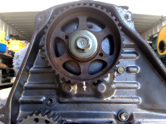
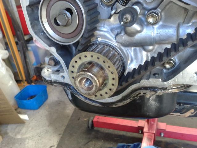
2: Your crank should already be positioned at TDC from a pervious step so slide the harmonic balancer onto the crank and ensure that the timing marks line up correctly. Once done, slip the balancer off and put aside.
Note also that I have painted all of the timing marks with a paint pen. I didn't do it for me, more for you to see as some photos can be difficult to see fine detail.
Download Full Size Image

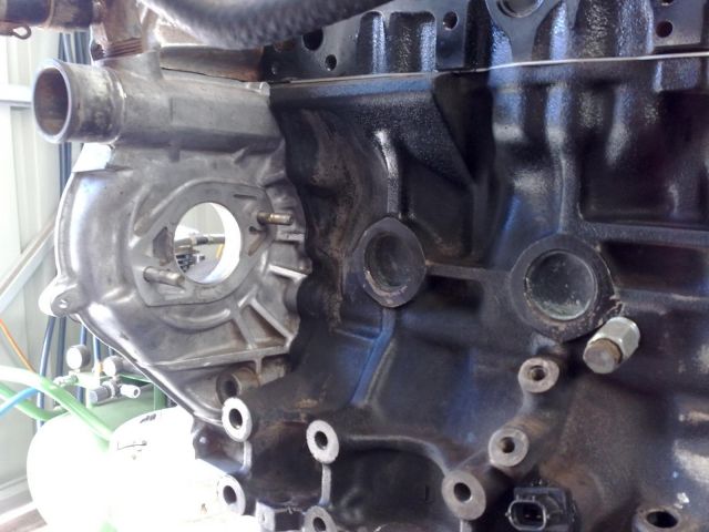
3: Shown in this photo is the location of the injector pump. The 2 studs and the 2 vertical bolt holes next to the right core plug are the puppies we're interested in for the next step.
Download Full Size Image
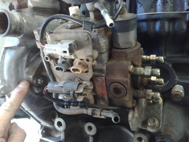
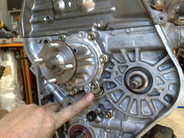
4: Position the injector pump and finger tighten the nuts but tighten the bolts. If you look where the rear bracket meets the rear of the pump you will notice a single nut. Slightly loosen this one up to the point where the pump can swivel on studs.
Where I'm pointing in the photo below you'll see a mark on the timing cover, and one on the injector pump. Line these up and tighten the 2 nuts on the timing cover, and the nut on the swivel point on the bracket.
Double check to ensure that the marks meet up. These marks are for the factory timing for the injector pump.
Download Full Size Image
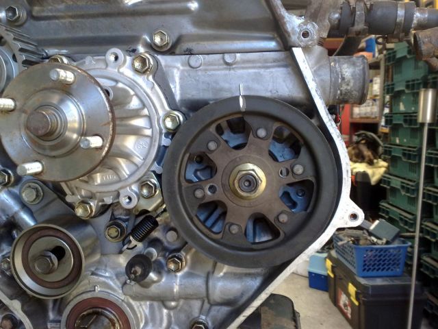
5: Postion and install the water pump and gasket. Make sure that you place the timing belt tensioner spring bracket onto the bolt hole in the postion located in the photo below.
Download Full Size Image
6: Place the timing belt tensioner into position and finger tighten the bolt on the bearing, but tighten the the other 2 bolts up.
Place the spring into position and use a pair of long-nosed pliers on the right side to assist with hooking over the bracket.
Using a screwdriver, lever the tensioner away from the spring (left) and tighten to keep the tension on the spring.
Download Full Size Image

7: Position and bolt up the idler pulley. That's the gear looking thingo to the upper-left of the water pump.
Download Full Size Image

8: Place the key into the keyway on the cam for the cam pulley.
Download Full Size Image

9: Silp the cam gear pulley onto the cam and tighten to 85 Nm.
The easiest way to tighten this without spinning the cam is to place a bolt into the cam gear, there are 2 holes. Place the socket and torque wrench onto the bolt and wedge an engineer's screwdriver between the bolt and the socket and apply opposite force as you tension the bolt. It worked for me.
Once done, make sure that the timing marks are correctly aligned.
Download Full Size Image
10: Silp the injector pump pulley onto the shaft and tighten to 64 Nm. Again, use the same principle to tighten the nut as in the step above.
Again, make sure that the timing marks are correctly aligned once tightened.
Download Full Size Image
11: Slip the crank sprocket over the crankshaft.
Download Full Size Image

12: Before staring this step, again, make sure that all of the timing marks are aligned correctly.
Starting at the crank sprocket, wrap the timing belt around the bottom and pinch at the sides.
Feed the belt over the tensioner and allow the top of the belt to flop over the water pump.
Download Full Size Image
13: Bring the belt over the injector pump pulley. While doing this, keep the pinch on the crank sprocket.
Download Full Size Image

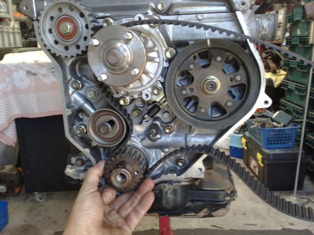
14: Feed the belt over the top of the cam gear and over the idler pulley. Still keep the pinch on the crank sprocket.
Download Full Size Image

15: Loosen the tensioner bolt so it rests on the timing belt.
Refit the harmonic balancer pulley bolt and turn the engine 4 complete rotations to ensure that the timing marks are aligned again. Remove the harmonic balancer pulley bolt.
Tighten the tensioner bolt to 44 Nm.
Download Full Size Image

16: Slip the crank sprocket belt retainer guide over the crank.
Download Full Size Image
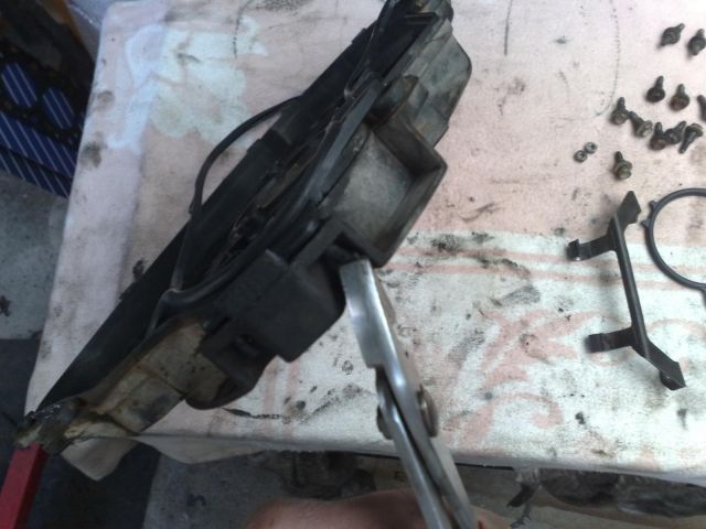
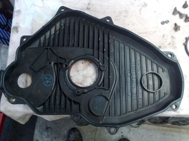
17: Shown in the photo below are the part for the timing cover.
Download Full Size Image

18: Position the 2 pins on the gasket into the lower part of the timing cover. This is the start point for fitting the gasket.
Download Full Size Image

19: Use a pair of pliers to GENTLY pull the pins through the holes to lock the pins in the cover.
Download Full Size Image
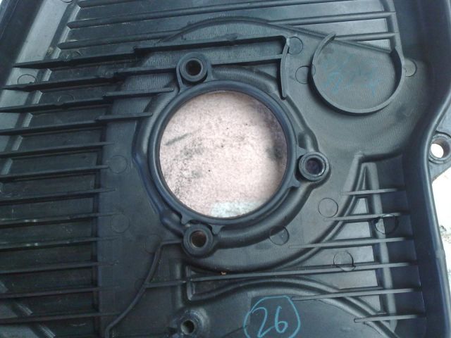
20: Place the gasket over the 2 top holes on the top of the timing cover.
Download Full Size Image

21: Starting one side at a time, feed the gasket along the edge of the timing cover hole by hole until it's finished. Check to ensure that the gasket is seated correctly along all of the edge.
Download Full Size Image
22: Place the inner gasket on the timing cover. Start at the loop, then the 2 last holes.
Download Full Size Image
23: Place the timing cover onto the engine and check to ensure that the surfaces are free from kinks or misalignment. Place all of the bolts into the holes and tighten. Don't place any bolts into the top 2 holes as these are explained in the step below.
Download Full Size Image

24: Place the 2 timing cover studs into the top of the cover. These are the only studs and are for a bracket for a water crossover pipe.
Download Full Size Image
25: Place the crossover bracket into position and fix with nuts.
Download Full Size Image
1: Position the upper cover and nip up the 4 bolts into the head.
Download Full Size Image
2: Your crank should already be positioned at TDC from a pervious step so slide the harmonic balancer onto the crank and ensure that the timing marks line up correctly. Once done, slip the balancer off and put aside.
Note also that I have painted all of the timing marks with a paint pen. I didn't do it for me, more for you to see as some photos can be difficult to see fine detail.
Download Full Size Image
3: Shown in this photo is the location of the injector pump. The 2 studs and the 2 vertical bolt holes next to the right core plug are the puppies we're interested in for the next step.
Download Full Size Image
4: Position the injector pump and finger tighten the nuts but tighten the bolts. If you look where the rear bracket meets the rear of the pump you will notice a single nut. Slightly loosen this one up to the point where the pump can swivel on studs.
Where I'm pointing in the photo below you'll see a mark on the timing cover, and one on the injector pump. Line these up and tighten the 2 nuts on the timing cover, and the nut on the swivel point on the bracket.
Double check to ensure that the marks meet up. These marks are for the factory timing for the injector pump.
Download Full Size Image
5: Postion and install the water pump and gasket. Make sure that you place the timing belt tensioner spring bracket onto the bolt hole in the postion located in the photo below.
Download Full Size Image
6: Place the timing belt tensioner into position and finger tighten the bolt on the bearing, but tighten the the other 2 bolts up.
Place the spring into position and use a pair of long-nosed pliers on the right side to assist with hooking over the bracket.
Using a screwdriver, lever the tensioner away from the spring (left) and tighten to keep the tension on the spring.
Download Full Size Image
7: Position and bolt up the idler pulley. That's the gear looking thingo to the upper-left of the water pump.
Download Full Size Image
8: Place the key into the keyway on the cam for the cam pulley.
Download Full Size Image
9: Silp the cam gear pulley onto the cam and tighten to 85 Nm.
The easiest way to tighten this without spinning the cam is to place a bolt into the cam gear, there are 2 holes. Place the socket and torque wrench onto the bolt and wedge an engineer's screwdriver between the bolt and the socket and apply opposite force as you tension the bolt. It worked for me.
Once done, make sure that the timing marks are correctly aligned.
Download Full Size Image
10: Silp the injector pump pulley onto the shaft and tighten to 64 Nm. Again, use the same principle to tighten the nut as in the step above.
Again, make sure that the timing marks are correctly aligned once tightened.
Download Full Size Image
11: Slip the crank sprocket over the crankshaft.
Download Full Size Image
12: Before staring this step, again, make sure that all of the timing marks are aligned correctly.
Starting at the crank sprocket, wrap the timing belt around the bottom and pinch at the sides.
Feed the belt over the tensioner and allow the top of the belt to flop over the water pump.
Download Full Size Image
13: Bring the belt over the injector pump pulley. While doing this, keep the pinch on the crank sprocket.
Download Full Size Image
14: Feed the belt over the top of the cam gear and over the idler pulley. Still keep the pinch on the crank sprocket.
Download Full Size Image
15: Loosen the tensioner bolt so it rests on the timing belt.
Refit the harmonic balancer pulley bolt and turn the engine 4 complete rotations to ensure that the timing marks are aligned again. Remove the harmonic balancer pulley bolt.
Tighten the tensioner bolt to 44 Nm.
Download Full Size Image
16: Slip the crank sprocket belt retainer guide over the crank.
Download Full Size Image
17: Shown in the photo below are the part for the timing cover.
Download Full Size Image
18: Position the 2 pins on the gasket into the lower part of the timing cover. This is the start point for fitting the gasket.
Download Full Size Image
19: Use a pair of pliers to GENTLY pull the pins through the holes to lock the pins in the cover.
Download Full Size Image
20: Place the gasket over the 2 top holes on the top of the timing cover.
Download Full Size Image
21: Starting one side at a time, feed the gasket along the edge of the timing cover hole by hole until it's finished. Check to ensure that the gasket is seated correctly along all of the edge.
Download Full Size Image
22: Place the inner gasket on the timing cover. Start at the loop, then the 2 last holes.
Download Full Size Image
23: Place the timing cover onto the engine and check to ensure that the surfaces are free from kinks or misalignment. Place all of the bolts into the holes and tighten. Don't place any bolts into the top 2 holes as these are explained in the step below.
Download Full Size Image
24: Place the 2 timing cover studs into the top of the cover. These are the only studs and are for a bracket for a water crossover pipe.
Download Full Size Image
25: Place the crossover bracket into position and fix with nuts.
Download Full Size Image
#12
Posted 17 November 2010 - 11:32 AM
2LV8ETR
-
- Vice President
-
- 3017 posts
Grampa Spec Cockhead
- Real Name:Allen
- LocationArmadale WA
- Car(s):RB30DET R32 Gts-t Sedan, Hilux SSR-G Surf 4x4
- Bike(s):Hyosung GT250-R, My wife...
Step 11: Harmonic Balancer.
1: Slip the balancer onto the crank and nip up the bolt.
Download Full Size Image
2: Place 2 bolts into the back of the crank and slide an engineer's screwdriver through the bolts and engine stand.
Download Full Size Image
3: Tighten the balancer bolt to 167 Nm.
Download Full Size Image
1: Slip the balancer onto the crank and nip up the bolt.
Download Full Size Image
2: Place 2 bolts into the back of the crank and slide an engineer's screwdriver through the bolts and engine stand.
Download Full Size Image
3: Tighten the balancer bolt to 167 Nm.
Download Full Size Image
#13
Posted 17 November 2010 - 11:59 AM
2LV8ETR
-
- Vice President
-
- 3017 posts
Grampa Spec Cockhead
- Real Name:Allen
- LocationArmadale WA
- Car(s):RB30DET R32 Gts-t Sedan, Hilux SSR-G Surf 4x4
- Bike(s):Hyosung GT250-R, My wife...
Step 12: Injectors.
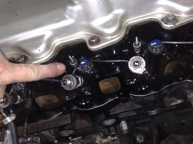
1: In the image below, I am pointing to the injector port. The other one is for the glow pugs. You can't get this wrong as the injector port is larger in diameter than the glow plug port. You can also see the seal positioned in the port.
If you manage to fit an injector into the glow plug port, you deserve a sticky gold star for outstanding effort.
Download Full Size Image

2: This is the injector seal. If you're rebulding your engine, I'd advise replacing these as there are fine holes in the seal to carry the fuel from the rail to the injector. They're cheap, don't skimp!
Download Full Size Image

3: Place the seal into the port, then screw the injector into place. Nip up the injector and place a small parts bag over the end to keep foreign matter out.
Repeat the step for the other 3 injectors.
Download Full Size Image
4: Place the fuel rail onto the injectors and tighten up the retaining nuts on all 4 injectors. Make sure that the inlet of the rail is at the pump end as shown in the image below.
Download Full Size Image

5: Install the fuel line between the rail and the pump and tighten the hose clamps. Use worm drive clamps, not the stupid compression style type.
Download Full Size Image

1: In the image below, I am pointing to the injector port. The other one is for the glow pugs. You can't get this wrong as the injector port is larger in diameter than the glow plug port. You can also see the seal positioned in the port.
If you manage to fit an injector into the glow plug port, you deserve a sticky gold star for outstanding effort.
Download Full Size Image
2: This is the injector seal. If you're rebulding your engine, I'd advise replacing these as there are fine holes in the seal to carry the fuel from the rail to the injector. They're cheap, don't skimp!
Download Full Size Image
3: Place the seal into the port, then screw the injector into place. Nip up the injector and place a small parts bag over the end to keep foreign matter out.
Repeat the step for the other 3 injectors.
Download Full Size Image
4: Place the fuel rail onto the injectors and tighten up the retaining nuts on all 4 injectors. Make sure that the inlet of the rail is at the pump end as shown in the image below.
Download Full Size Image
5: Install the fuel line between the rail and the pump and tighten the hose clamps. Use worm drive clamps, not the stupid compression style type.
Download Full Size Image
#14
Posted 17 November 2010 - 12:12 PM
2LV8ETR
-
- Vice President
-
- 3017 posts
Grampa Spec Cockhead
- Real Name:Allen
- LocationArmadale WA
- Car(s):RB30DET R32 Gts-t Sedan, Hilux SSR-G Surf 4x4
- Bike(s):Hyosung GT250-R, My wife...
Step 13: Water Temperature Sender.
1: Slip the copper washer onto the thread of the sender unit and tighten. Again, use a new washer. Don't be stingy now!
Download Full Size Image

1: Slip the copper washer onto the thread of the sender unit and tighten. Again, use a new washer. Don't be stingy now!
Download Full Size Image
#15
Posted 17 November 2010 - 12:23 PM
2LV8ETR
-
- Vice President
-
- 3017 posts
Grampa Spec Cockhead
- Real Name:Allen
- LocationArmadale WA
- Car(s):RB30DET R32 Gts-t Sedan, Hilux SSR-G Surf 4x4
- Bike(s):Hyosung GT250-R, My wife...
Step 14: Glow Plugs.
1: Drop the glow plug into the port and tighten up. These don't use a washer to seal as they have a tapered thread.
Repeat for the other 3 plugs.
Download Full Size Image
1: Drop the glow plug into the port and tighten up. These don't use a washer to seal as they have a tapered thread.
Repeat for the other 3 plugs.
Download Full Size Image
#16
Posted 17 November 2010 - 12:52 PM
2LV8ETR
-
- Vice President
-
- 3017 posts
Grampa Spec Cockhead
- Real Name:Allen
- LocationArmadale WA
- Car(s):RB30DET R32 Gts-t Sedan, Hilux SSR-G Surf 4x4
- Bike(s):Hyosung GT250-R, My wife...
Step 15: Thermostat Housing.
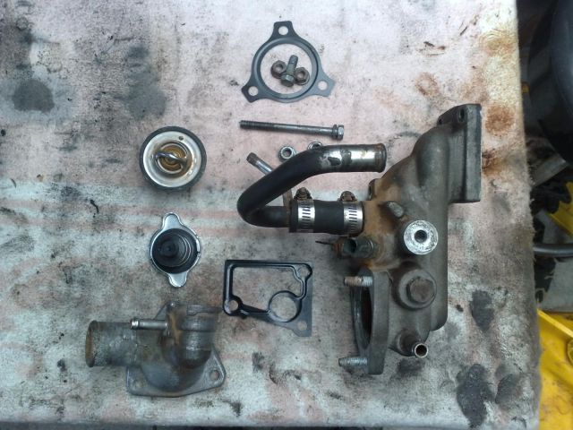
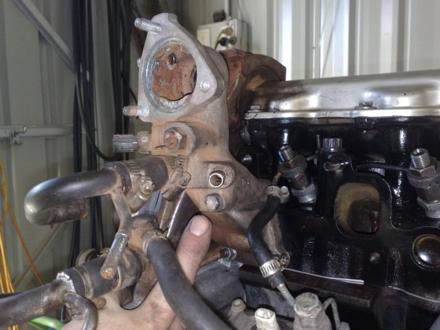
1: Below is an image of the housing and parts. Note that I have not removed the heater and turbo feed line. If you have removed these, then you can put them on at the end of this step, or after the engine is installed.
Download Full Size Image
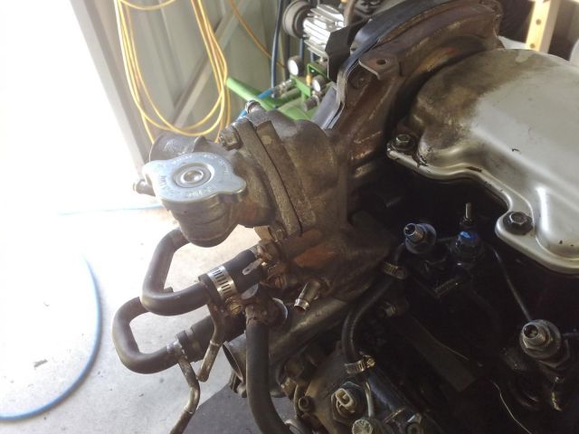
2: Place the gasket onto the lower housing studs and position the housing onto the block. Nip up the 2 lower nuts and there is a long bolt that I'm pointing at that will need to be installed. Tighten both nuts and the bolt to 19 Nm.
Download Full Size Image
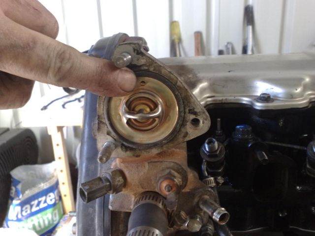
3: Position the thermostat into the housing with the jiggle valve to the top of the engine. Place the gasket onto the studs and position the housing outlet over the housing and tighten the 2 nuts and bolt to 19 Nm.
Download Full Size Image
4: Place the cap onto the housing and this is what it should all look like.
Download Full Size Image
1: Below is an image of the housing and parts. Note that I have not removed the heater and turbo feed line. If you have removed these, then you can put them on at the end of this step, or after the engine is installed.
Download Full Size Image
2: Place the gasket onto the lower housing studs and position the housing onto the block. Nip up the 2 lower nuts and there is a long bolt that I'm pointing at that will need to be installed. Tighten both nuts and the bolt to 19 Nm.
Download Full Size Image
3: Position the thermostat into the housing with the jiggle valve to the top of the engine. Place the gasket onto the studs and position the housing outlet over the housing and tighten the 2 nuts and bolt to 19 Nm.
Download Full Size Image
4: Place the cap onto the housing and this is what it should all look like.
Download Full Size Image
#17
Posted 17 November 2010 - 01:29 PM
2LV8ETR
-
- Vice President
-
- 3017 posts
Grampa Spec Cockhead
- Real Name:Allen
- LocationArmadale WA
- Car(s):RB30DET R32 Gts-t Sedan, Hilux SSR-G Surf 4x4
- Bike(s):Hyosung GT250-R, My wife...
Step 16: Intake Manifold.
1: Position the gasket onto the studs. It will only go one way and line up with the intake ports and studs/bolt holes.
Download Full Size Image
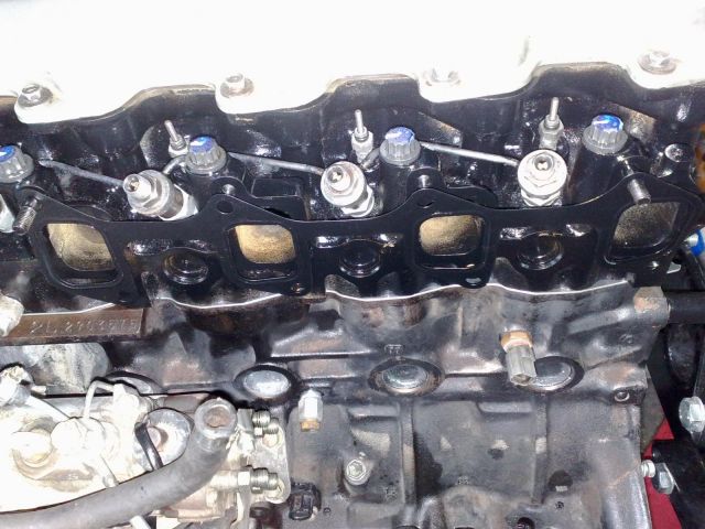
2: Position the manifold onto the studs and nip up the nuts and bolts to 17 Nm.
Note that I have left the venturi assembly and injector lines on the manifold. If you have removed these, then you should put them on now before the engine is installed to make the task easier.
Also note that I have modified and removed the EGR assembly. If you want to perform this modification, then go HERE to learn how it's done. If you don't want to perform the modification then install the EGR assembly before installing the engine.
Download Full Size Image
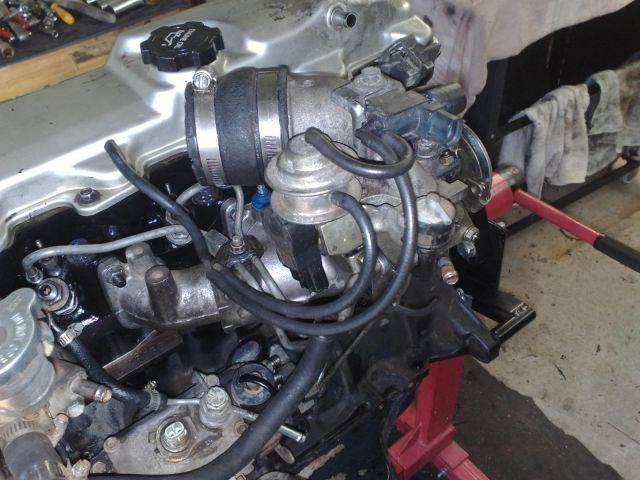
3: Position and install the injector lines onto the injectors. As stated previously, I left these connected to the inlet manifold so if you have removed them, enjoy your jigsaw puzzle.
Download Full Size Image

4: Position and install the injector lines onto the rear of the pump. Did you enjoy your puzzle?
Download Full Size Image

1: Position the gasket onto the studs. It will only go one way and line up with the intake ports and studs/bolt holes.
Download Full Size Image
2: Position the manifold onto the studs and nip up the nuts and bolts to 17 Nm.
Note that I have left the venturi assembly and injector lines on the manifold. If you have removed these, then you should put them on now before the engine is installed to make the task easier.
Also note that I have modified and removed the EGR assembly. If you want to perform this modification, then go HERE to learn how it's done. If you don't want to perform the modification then install the EGR assembly before installing the engine.
Download Full Size Image
3: Position and install the injector lines onto the injectors. As stated previously, I left these connected to the inlet manifold so if you have removed them, enjoy your jigsaw puzzle.
Download Full Size Image
4: Position and install the injector lines onto the rear of the pump. Did you enjoy your puzzle?
Download Full Size Image
#18
Posted 17 November 2010 - 02:17 PM
2LV8ETR
-
- Vice President
-
- 3017 posts
Grampa Spec Cockhead
- Real Name:Allen
- LocationArmadale WA
- Car(s):RB30DET R32 Gts-t Sedan, Hilux SSR-G Surf 4x4
- Bike(s):Hyosung GT250-R, My wife...
Step 17: Glow Plug Rail Installation.
1: Before you do anything, make sure that there is a couple of millimeters of clearance between the insulator ont the glow plug, and the nut on the top thread. If the nut is too close to the insulator, you will crack it when it comes time to tighten the assembly up.
2: Look at the rail. There is a solitary hole on the opposite side of the 4 glow plug mounting holes. Slip this hole onto the underside of the inlet manifold, where you will see an insulator. Position the rail onto the plugs, spin the nuts onto the thread and tighten. Again, make sure there is clearance between the insulator and the first nut.
Download Full Size Image
#19
Posted 17 November 2010 - 02:22 PM
2LV8ETR
-
- Vice President
-
- 3017 posts
Grampa Spec Cockhead
- Real Name:Allen
- LocationArmadale WA
- Car(s):RB30DET R32 Gts-t Sedan, Hilux SSR-G Surf 4x4
- Bike(s):Hyosung GT250-R, My wife...
Step 18: Dipstick Sleeve Installation.
1: Slip the dipstick sleeve between the inlet manifold and insert it into the hole. Using a hammer and an appropriate sized spanner, tap the sleeve into position until the hex rests against the block.
Download Full Size Image

1: Slip the dipstick sleeve between the inlet manifold and insert it into the hole. Using a hammer and an appropriate sized spanner, tap the sleeve into position until the hex rests against the block.
Download Full Size Image
#20
Posted 17 November 2010 - 02:28 PM
2LV8ETR
-
- Vice President
-
- 3017 posts
Grampa Spec Cockhead
- Real Name:Allen
- LocationArmadale WA
- Car(s):RB30DET R32 Gts-t Sedan, Hilux SSR-G Surf 4x4
- Bike(s):Hyosung GT250-R, My wife...
Step 19: Engine Lifting Hangers.
1: There are 2 of these hangers that are bolted to the head. One is behind the thermostat housing, and the other is at the opposite side and end of the head. Locate them and tighten the 2 bolts holding each one on.
Download Full Size Image
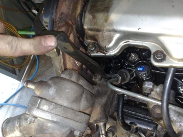
Download Full Size Image

1: There are 2 of these hangers that are bolted to the head. One is behind the thermostat housing, and the other is at the opposite side and end of the head. Locate them and tighten the 2 bolts holding each one on.
Download Full Size Image
Download Full Size Image


Community Forum Software by IP.Board
Licensed to: West Coast Cruisers, 2012

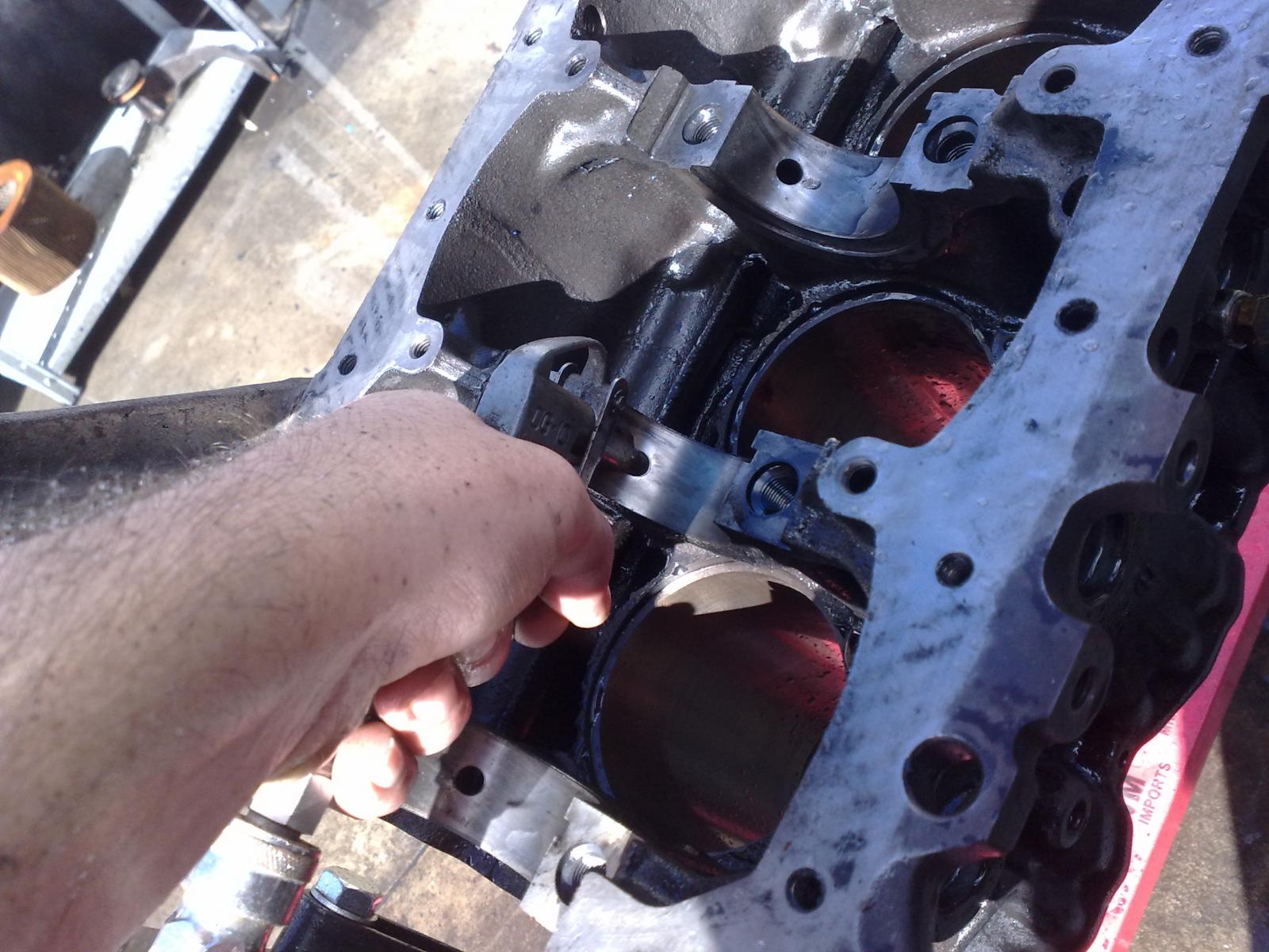
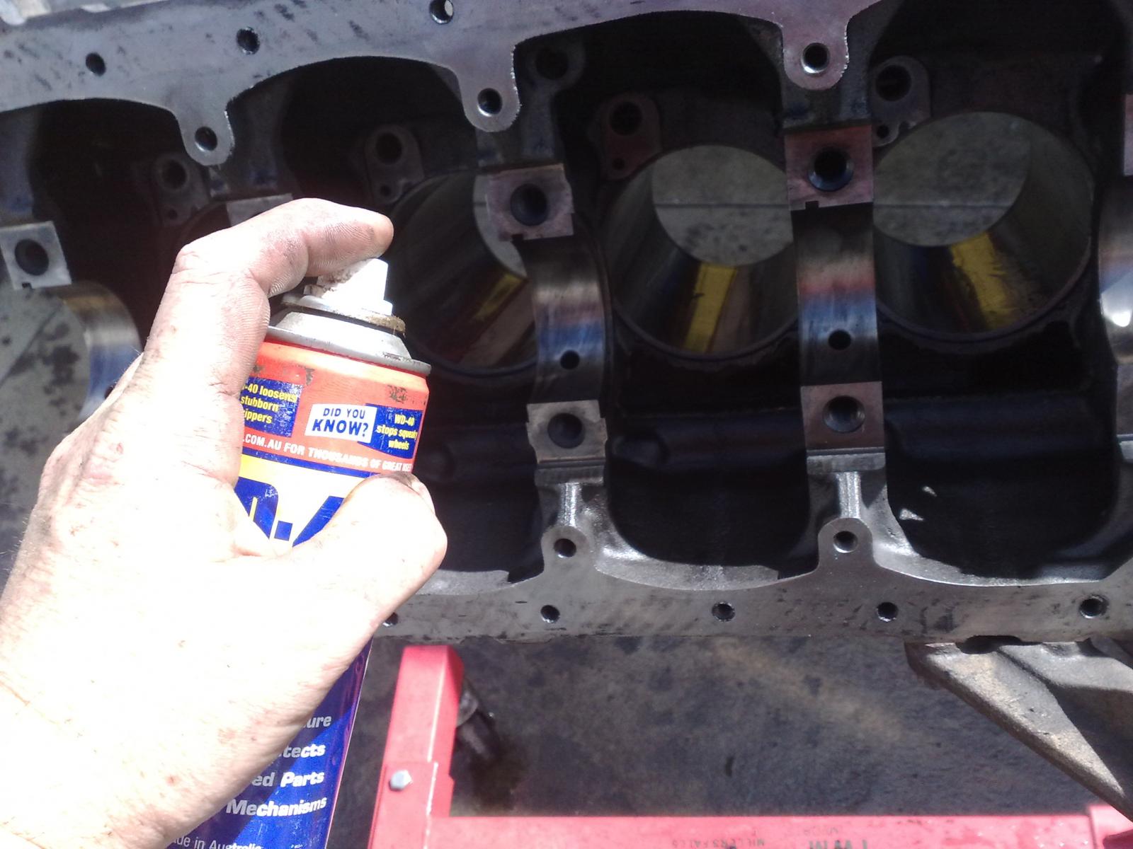
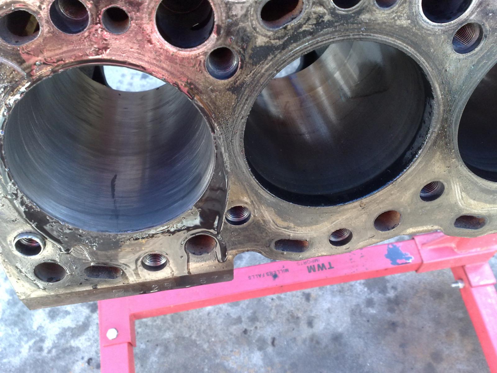
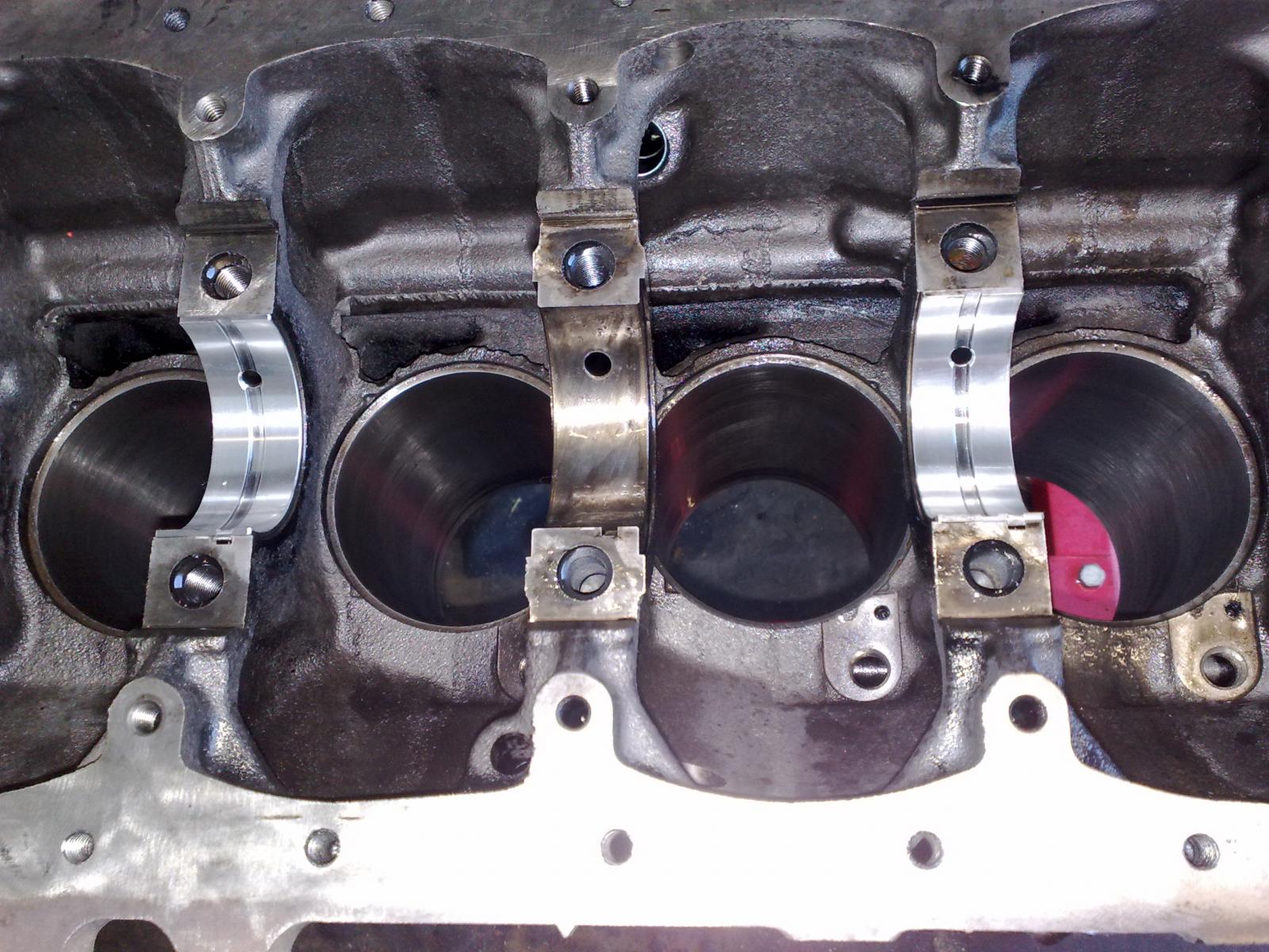
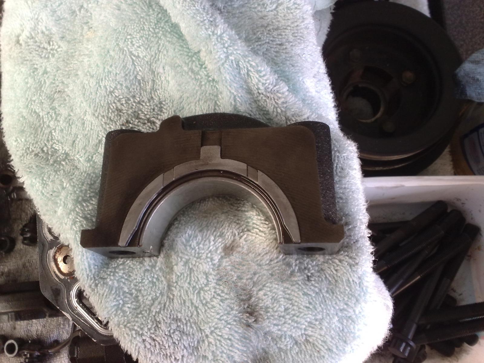
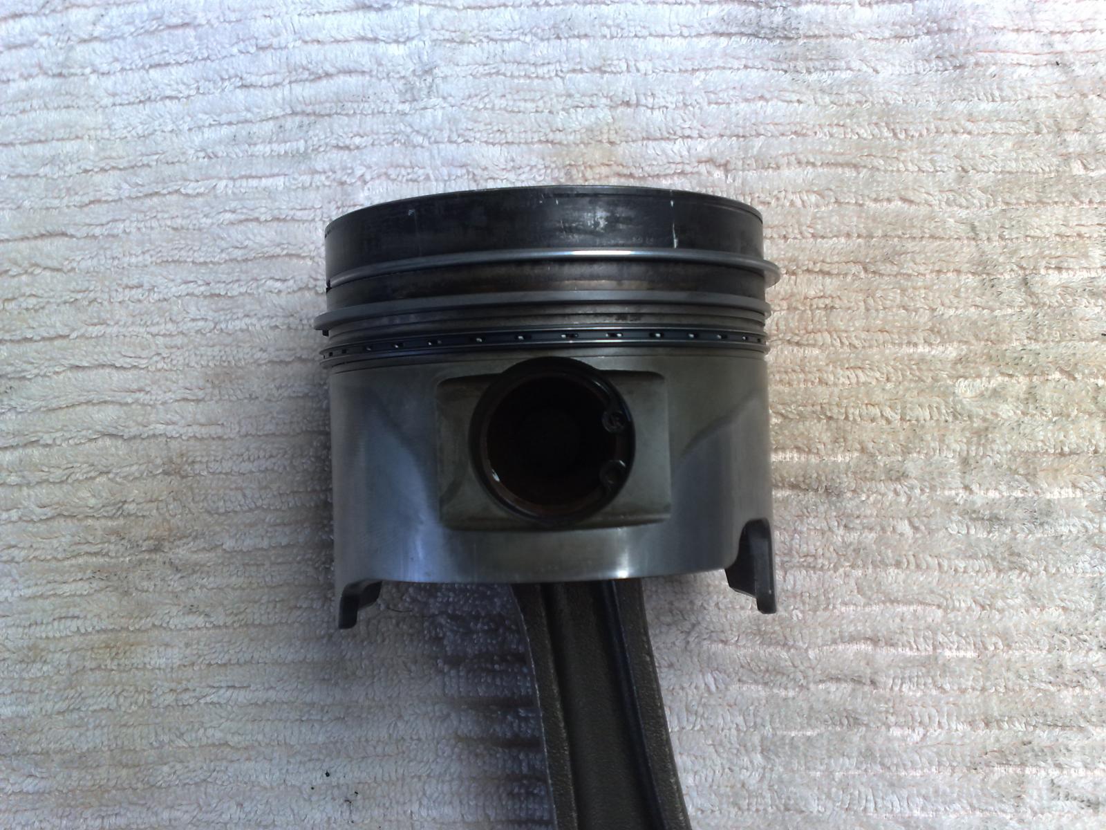
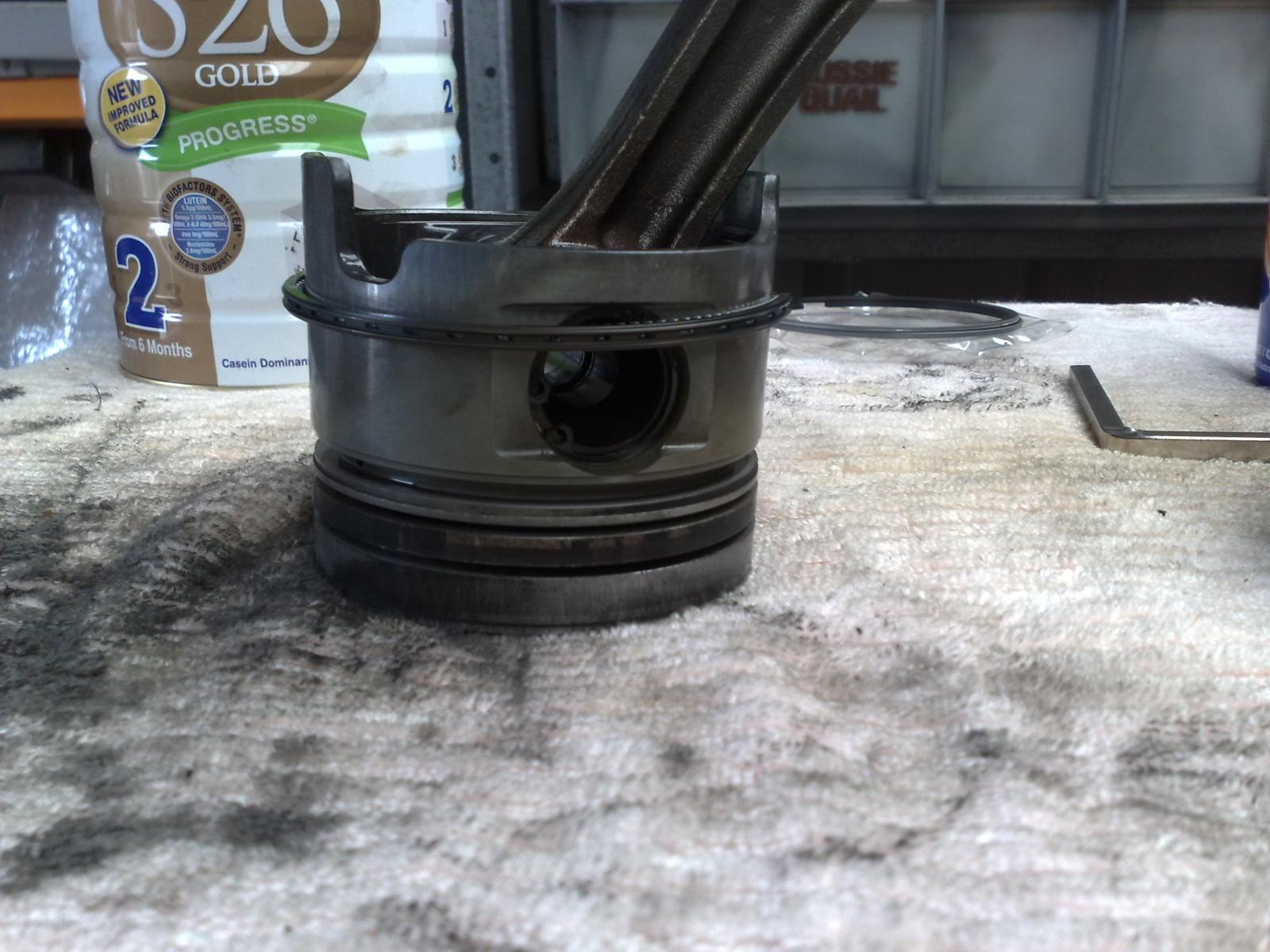
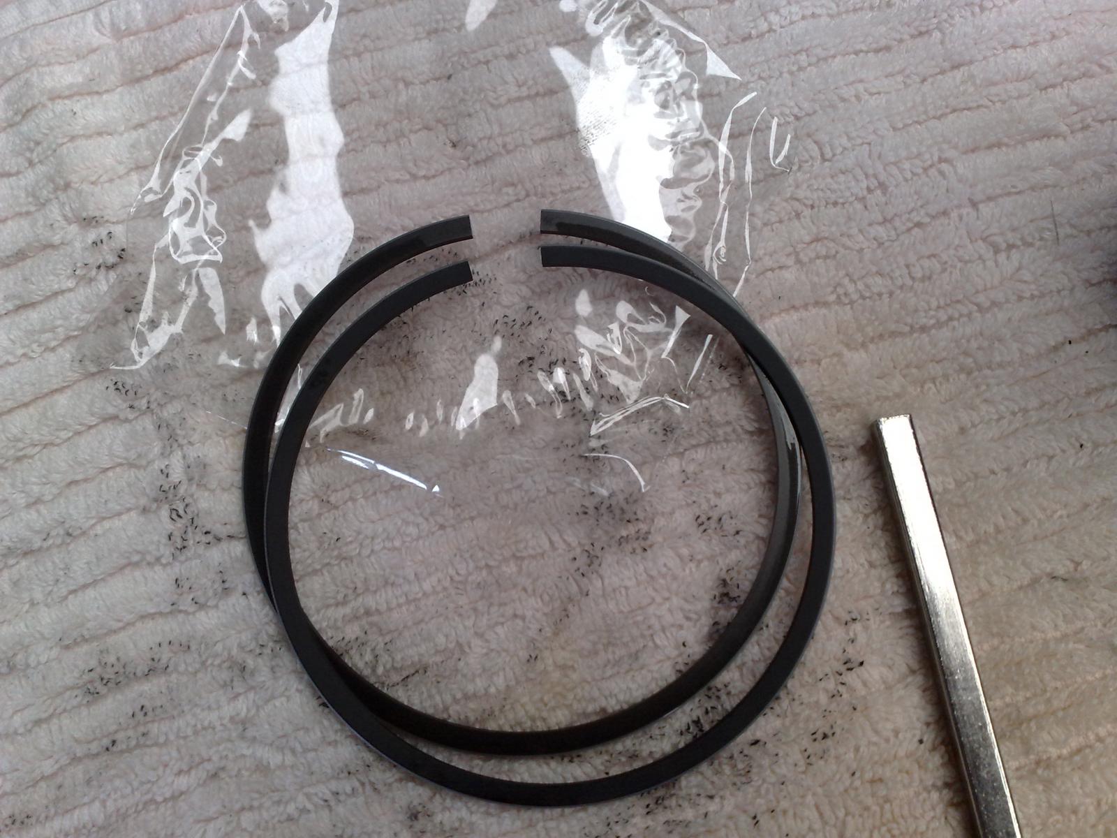
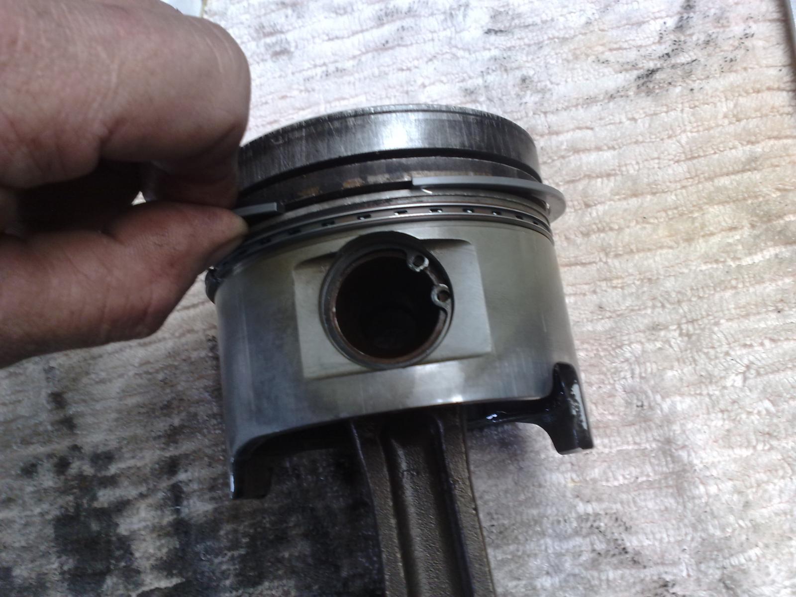
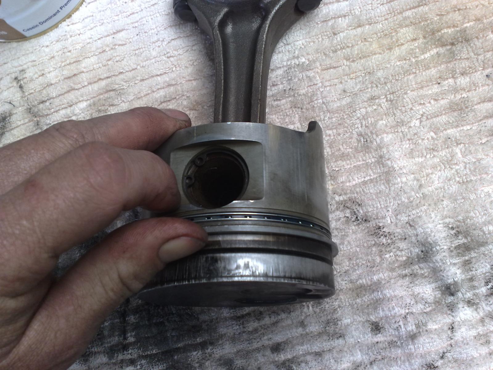
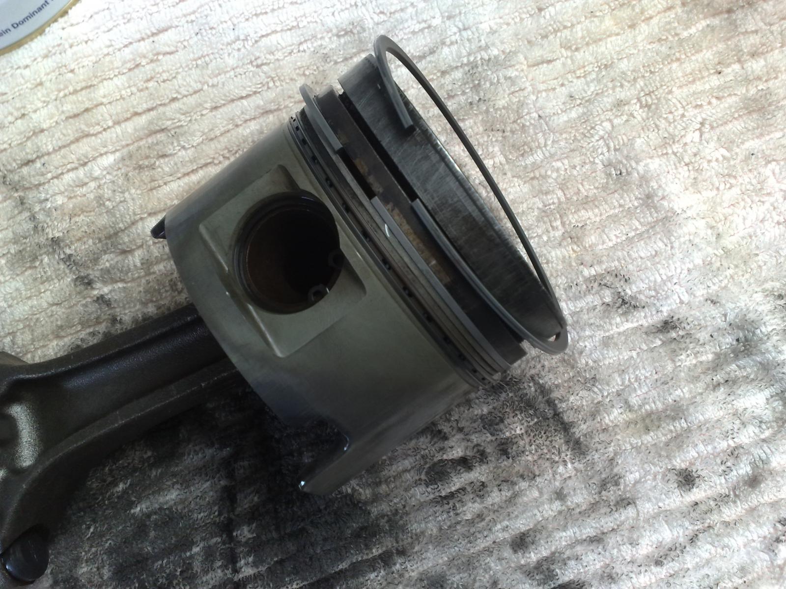
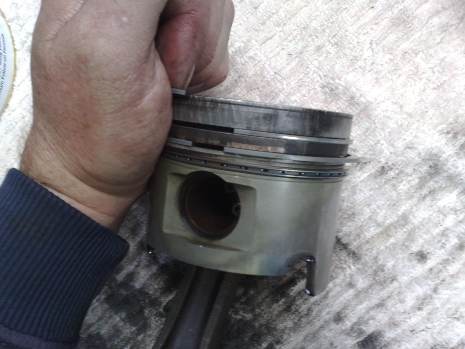
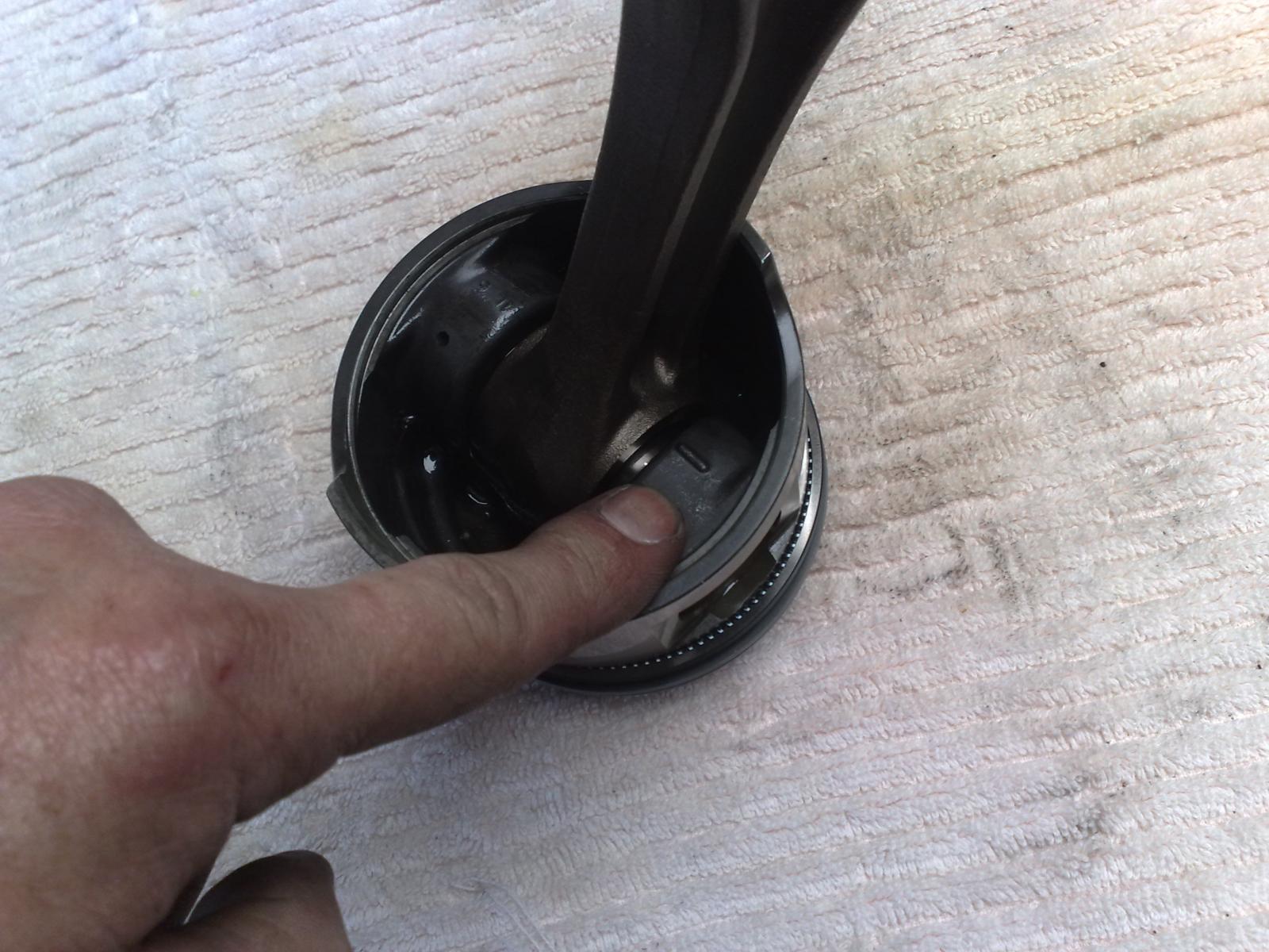
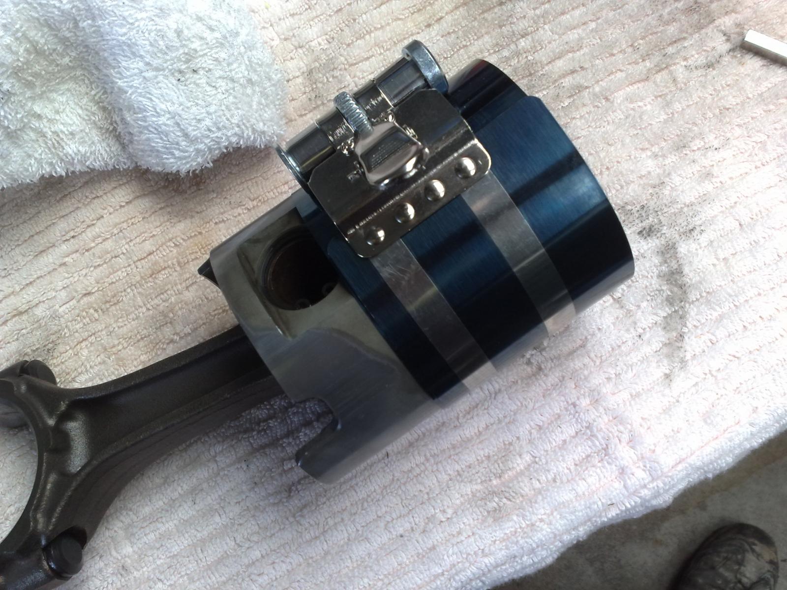
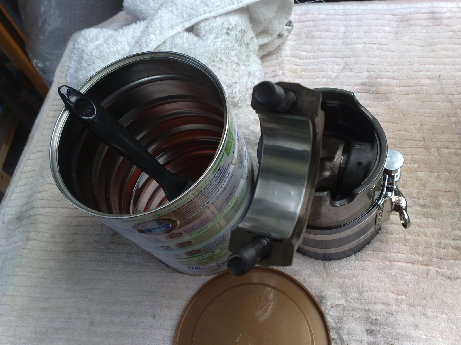
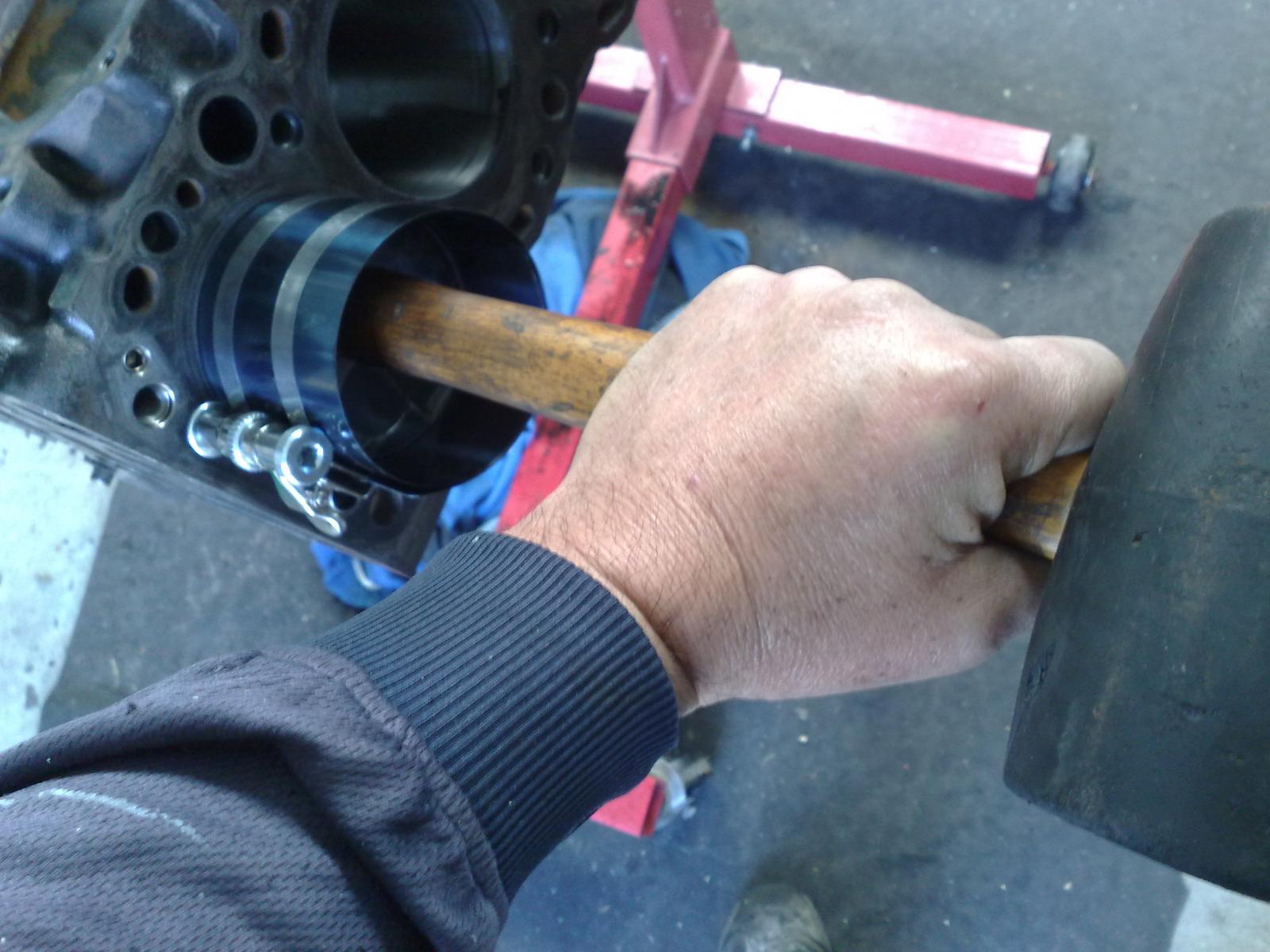
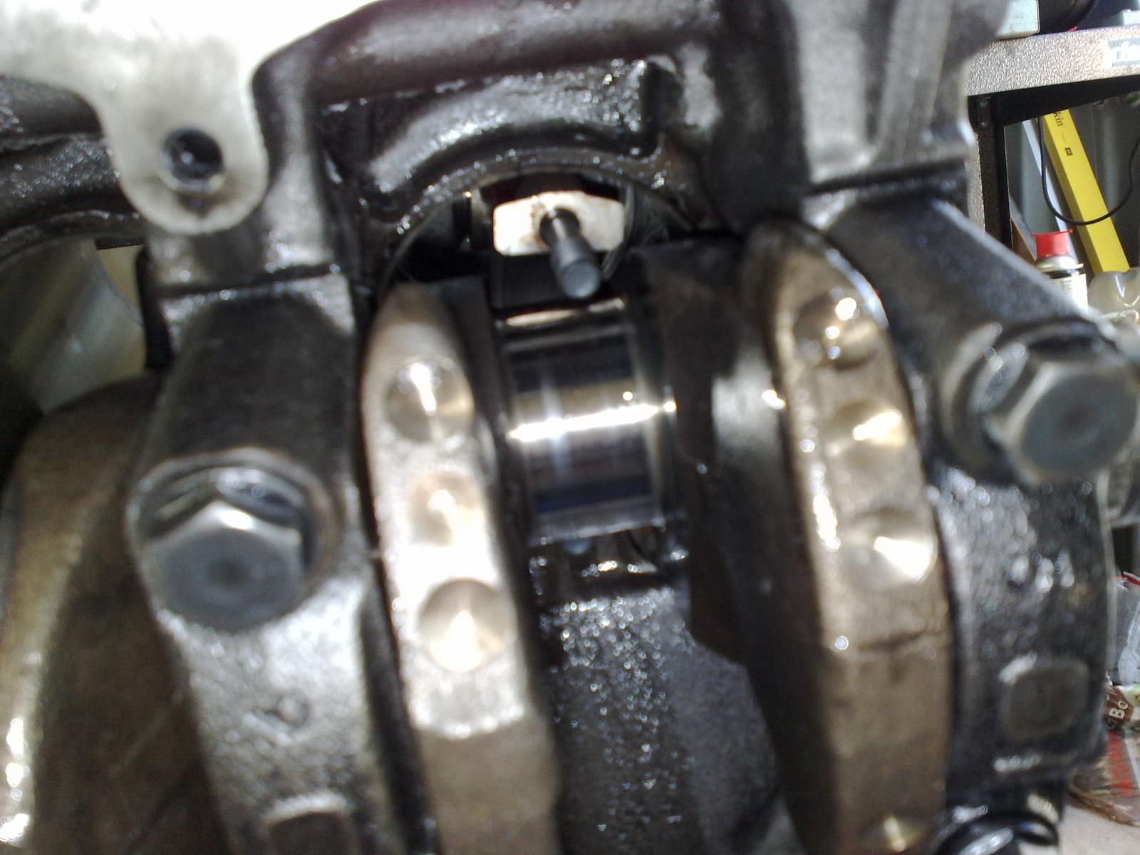
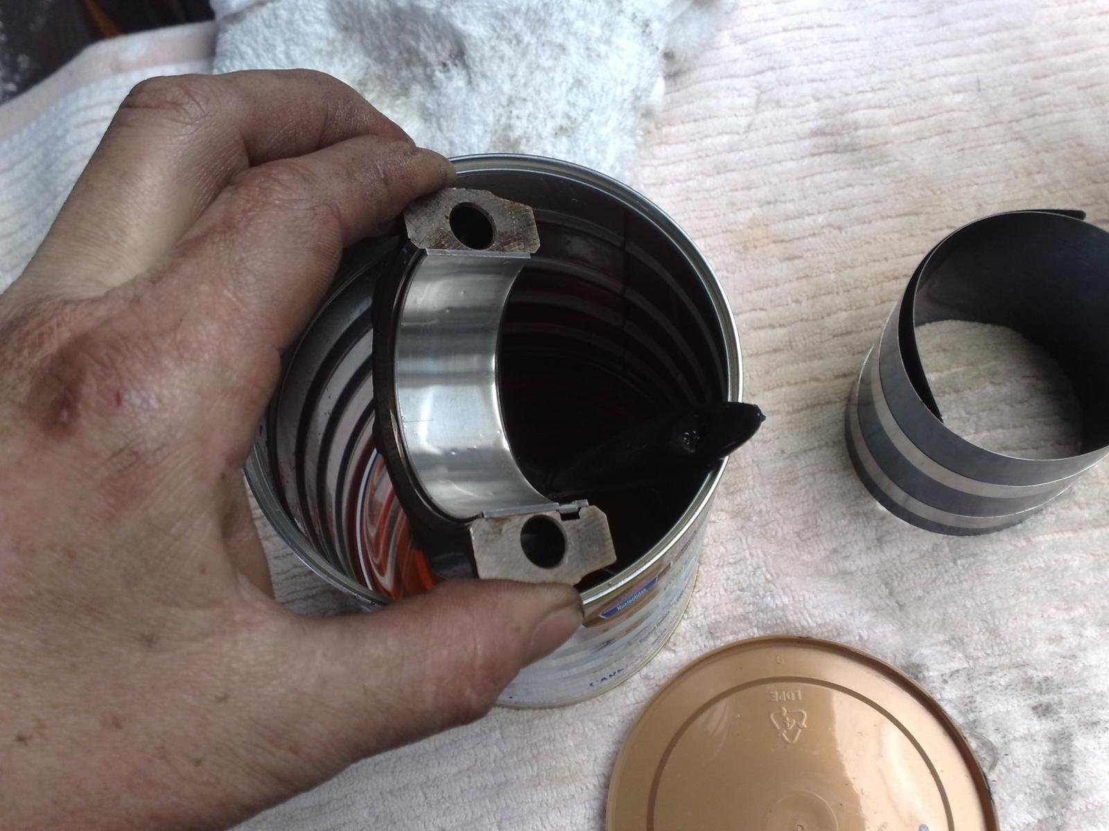
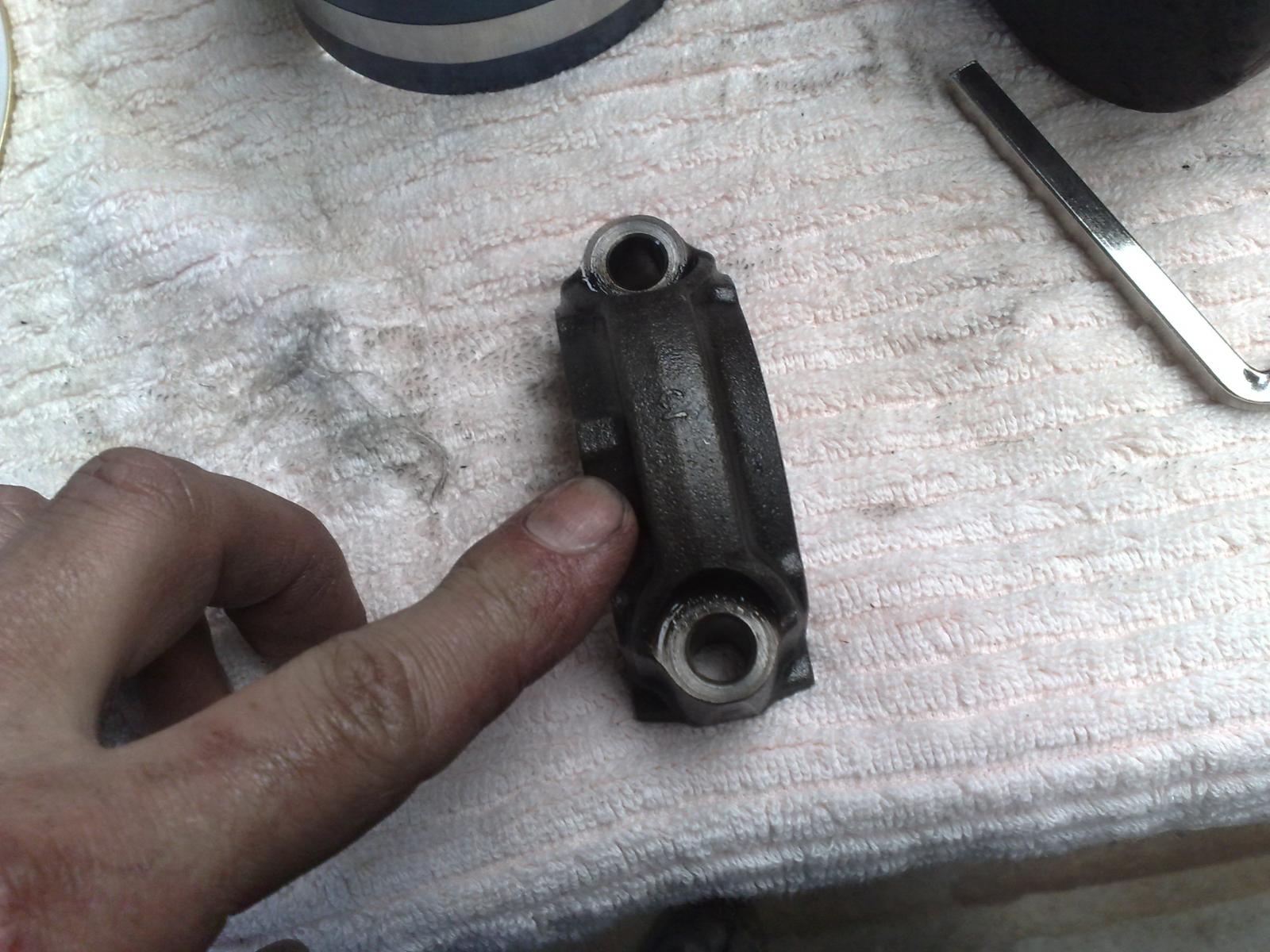
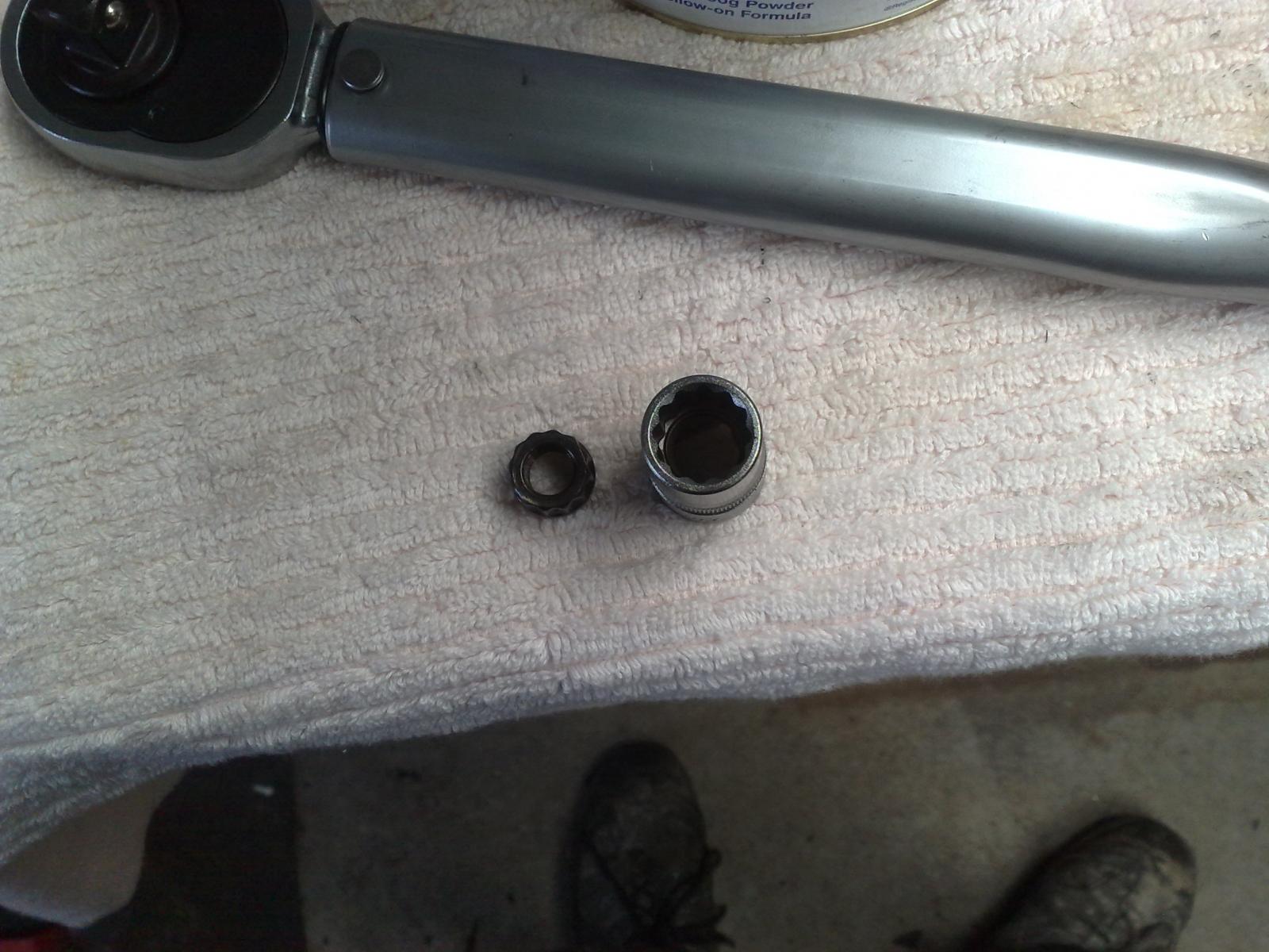
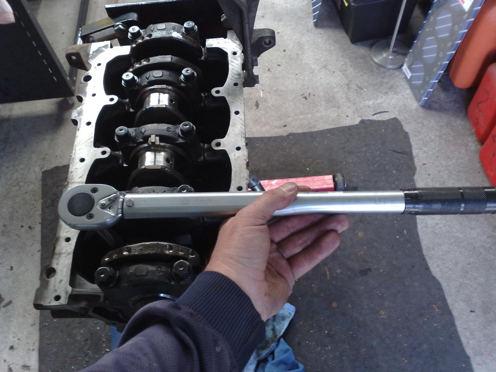
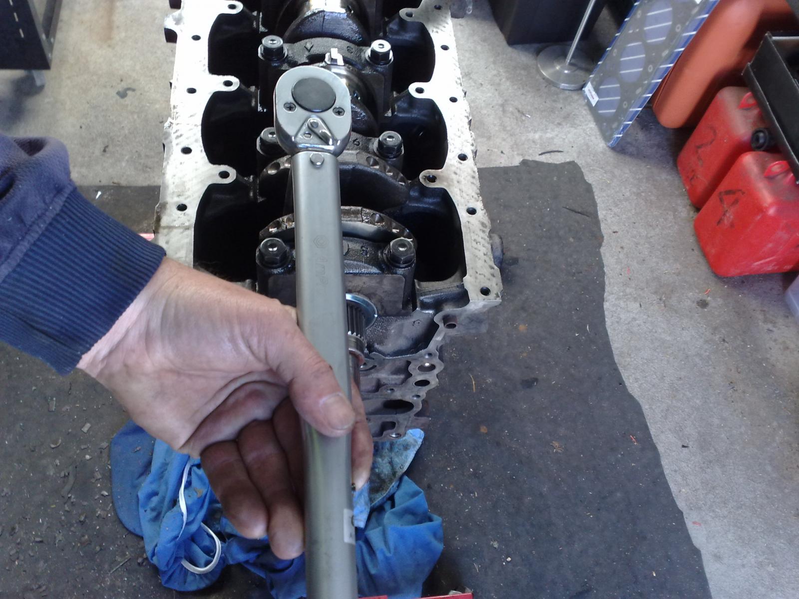
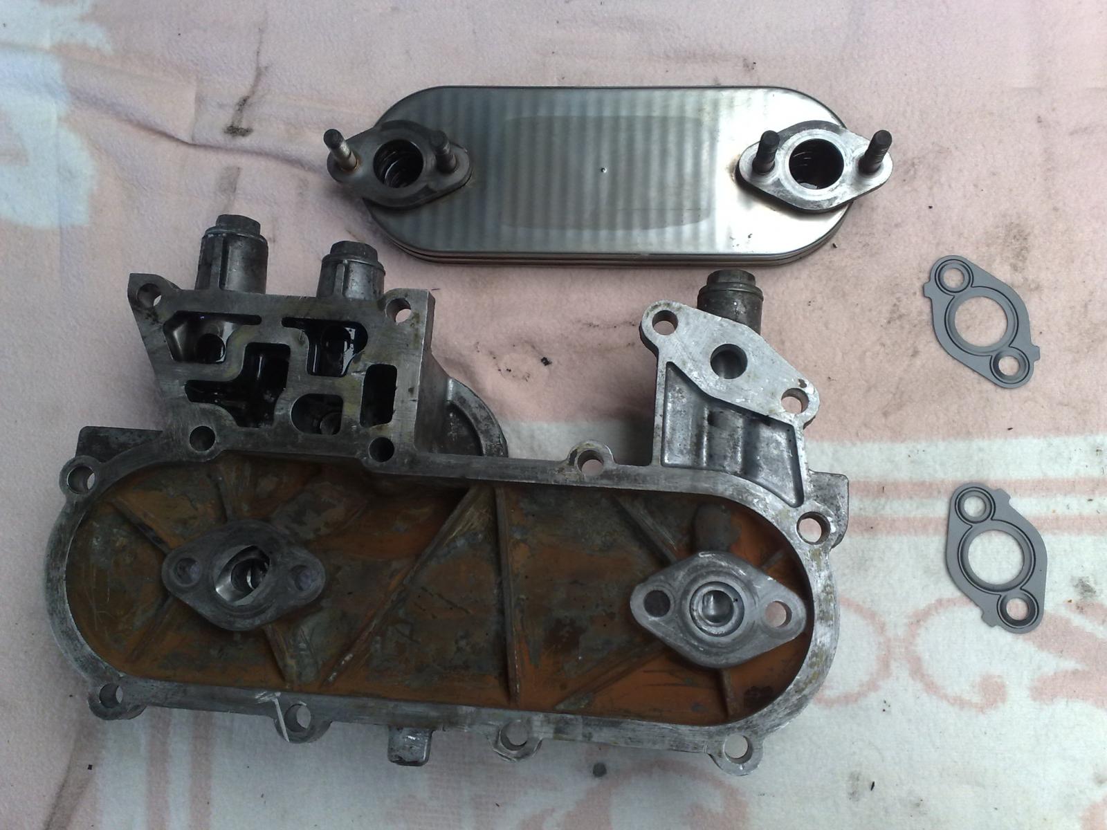
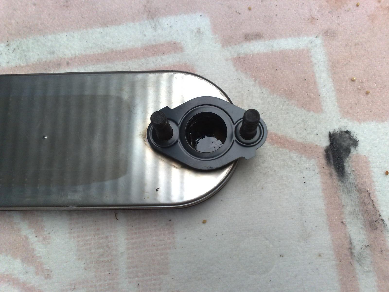
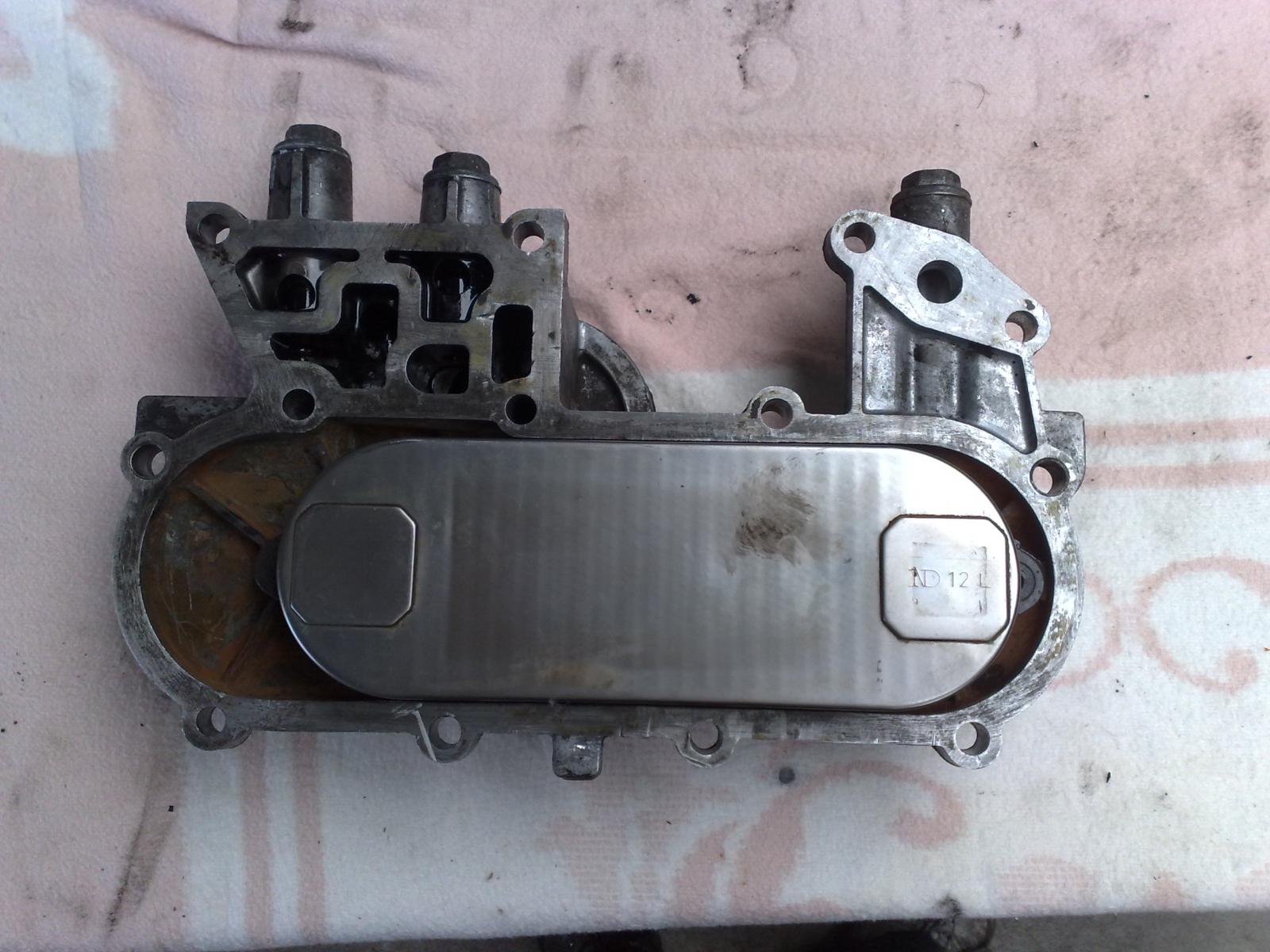
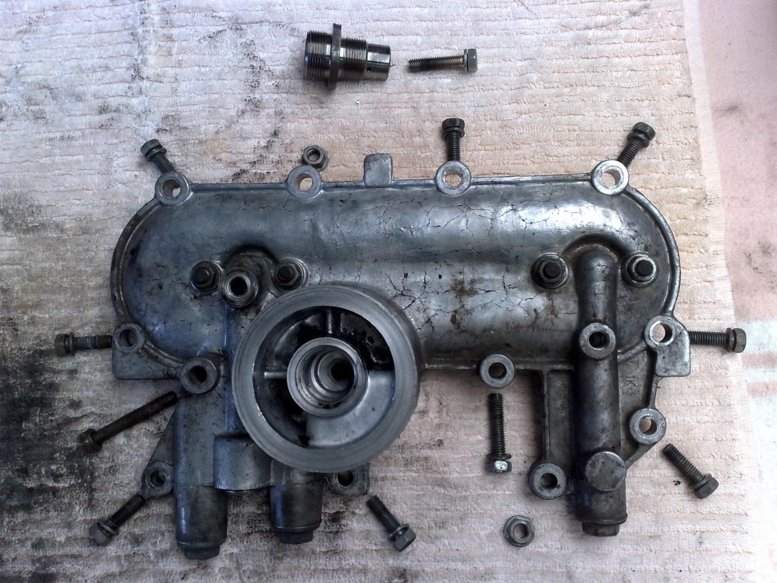
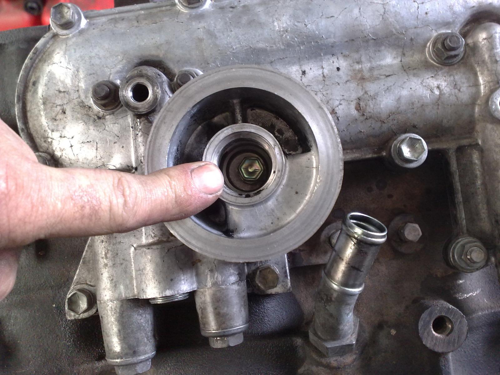
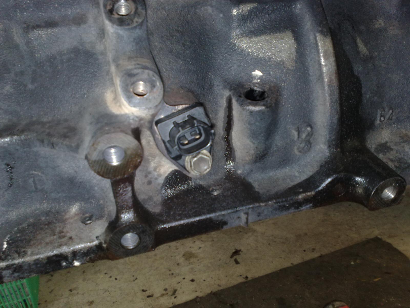
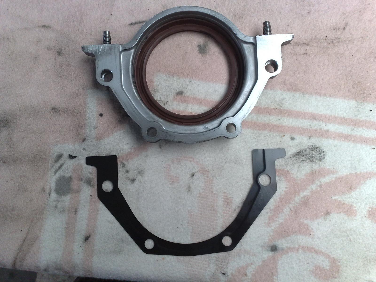
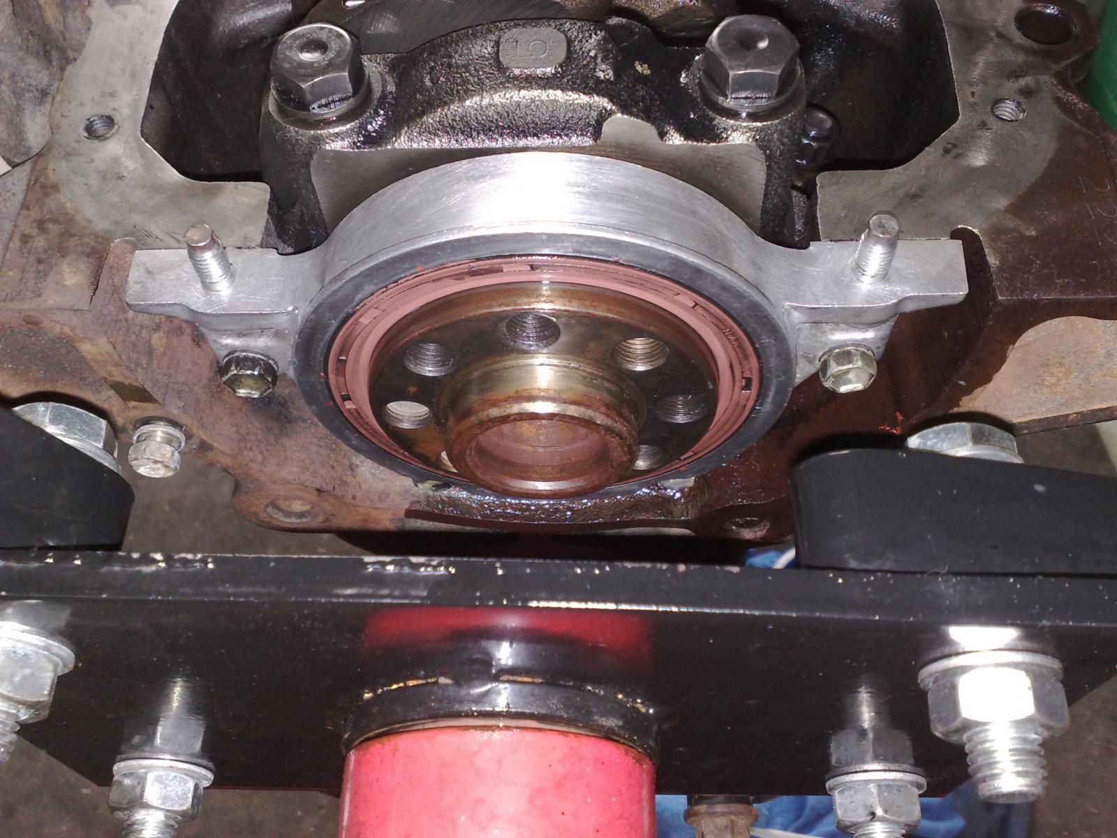
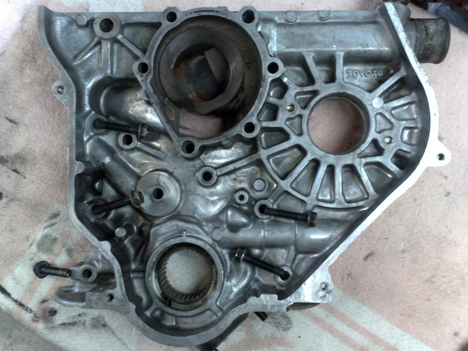
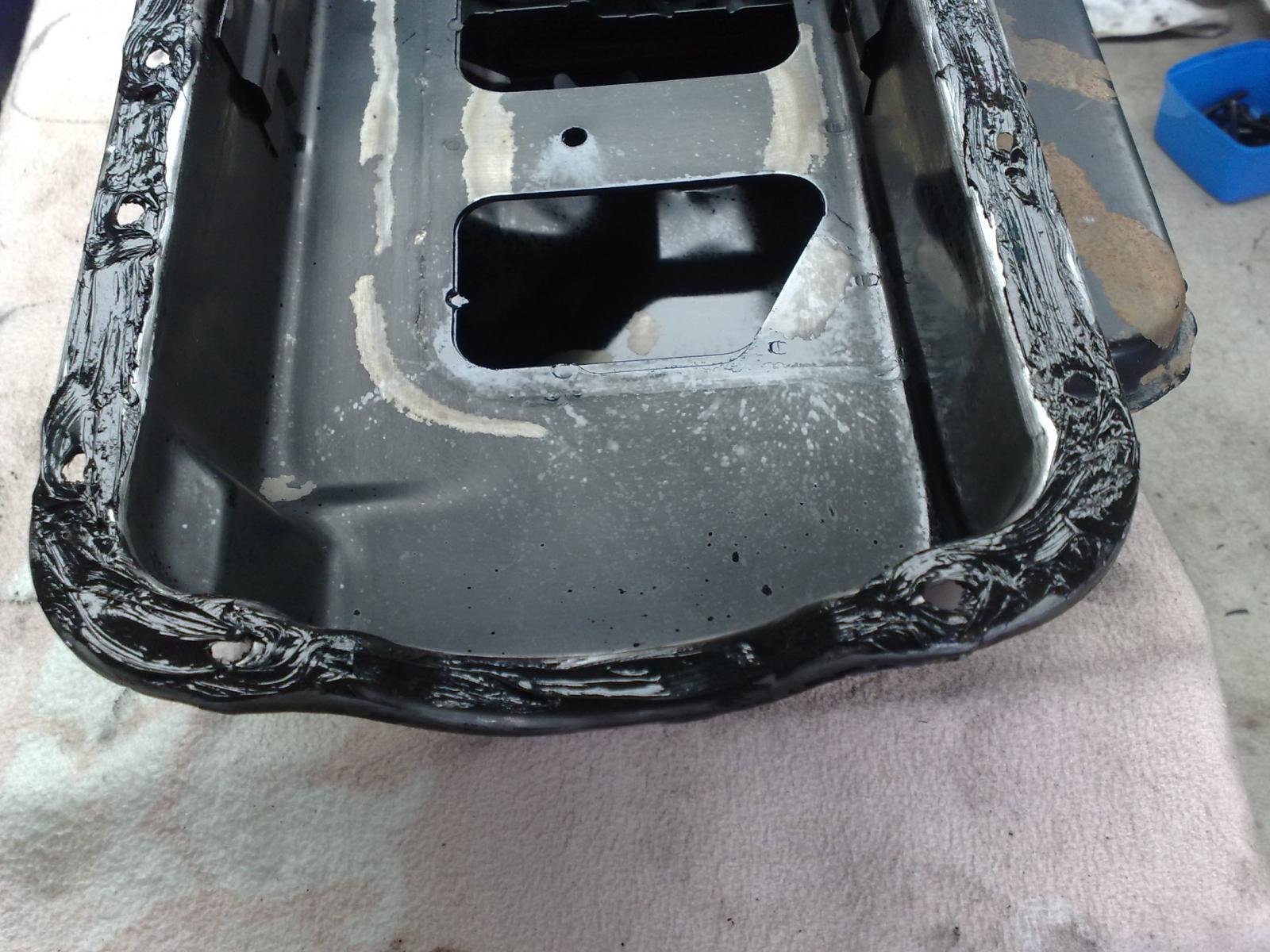
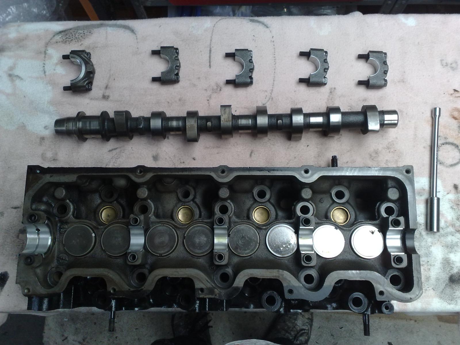
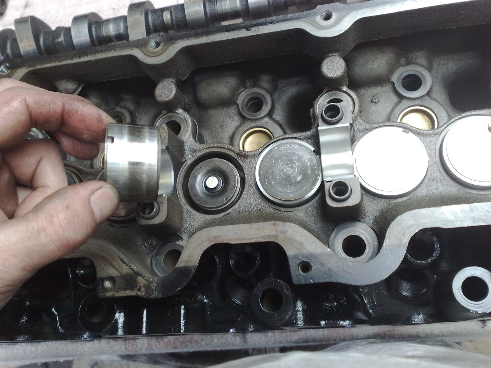
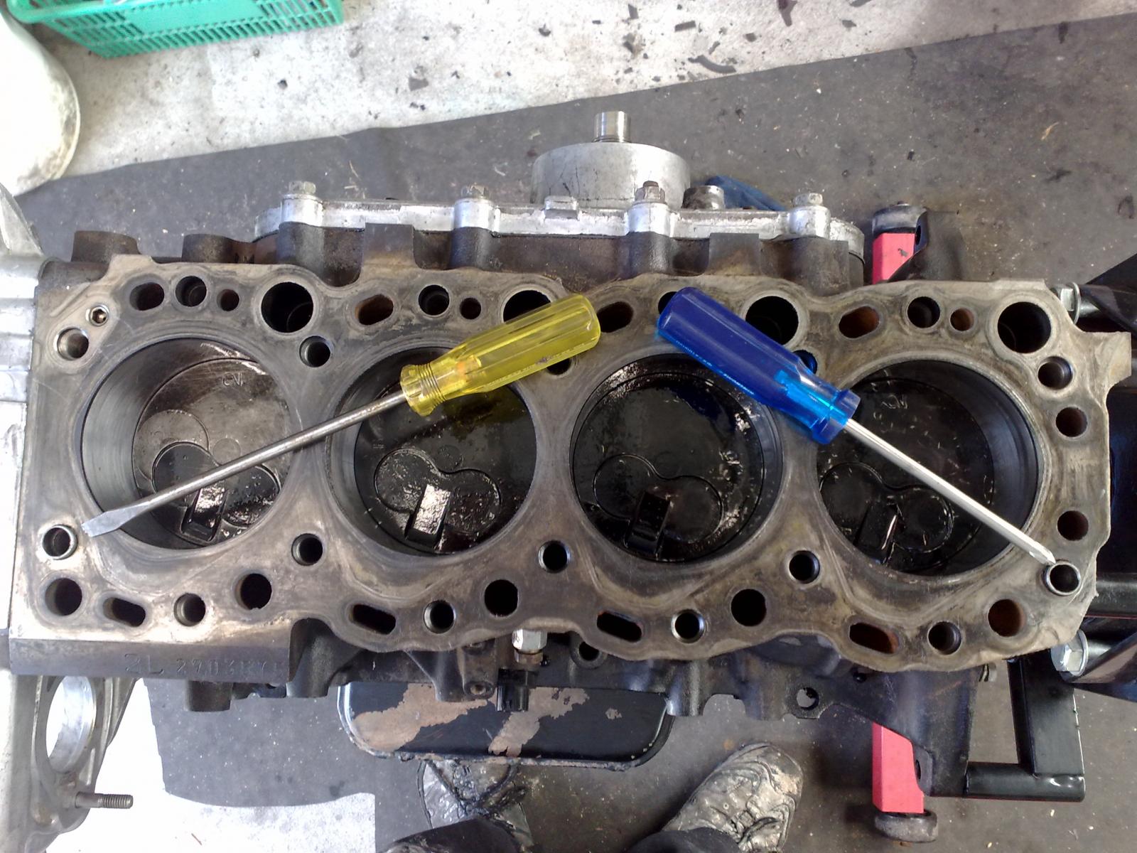
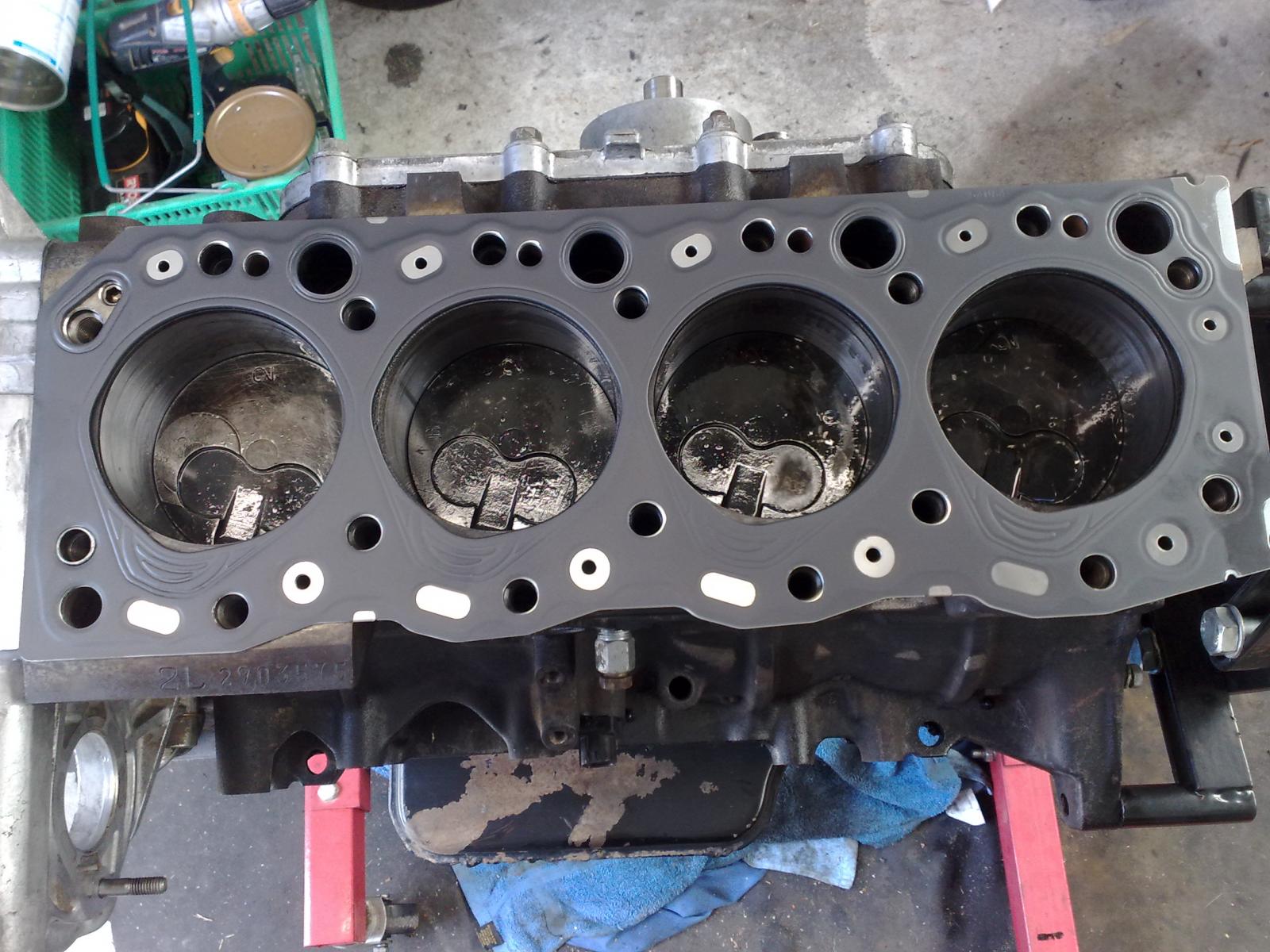
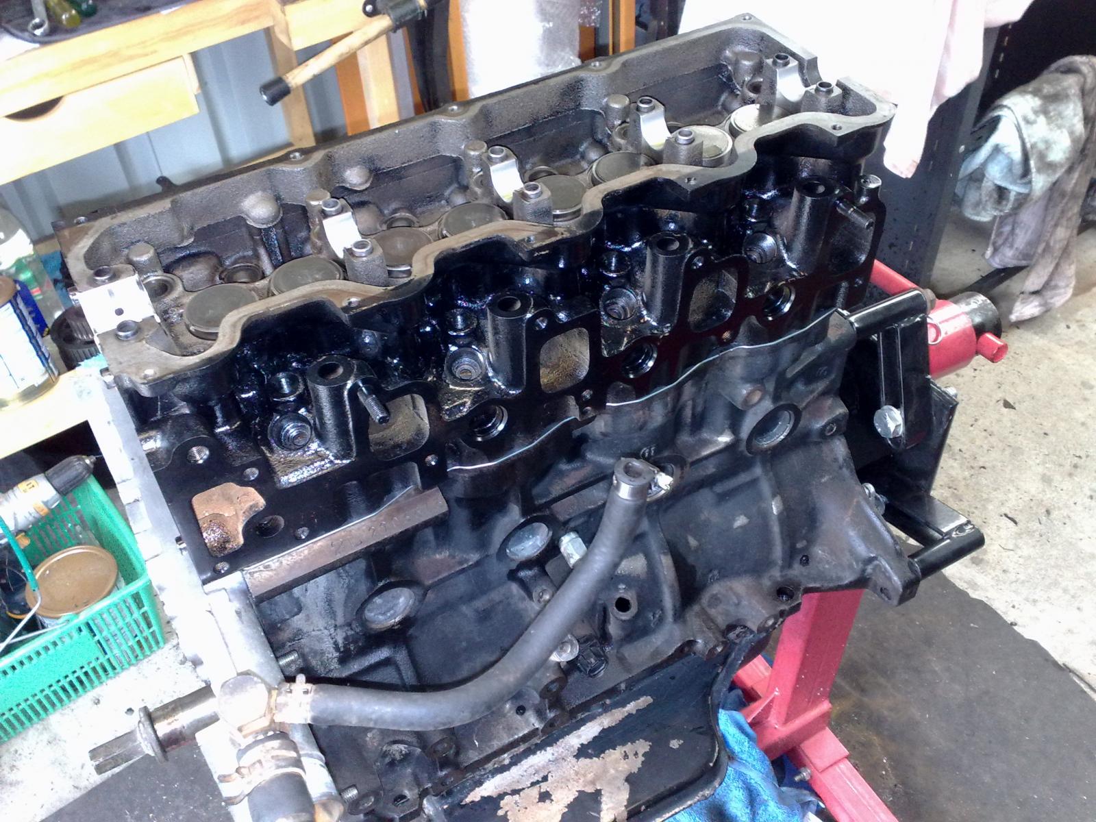
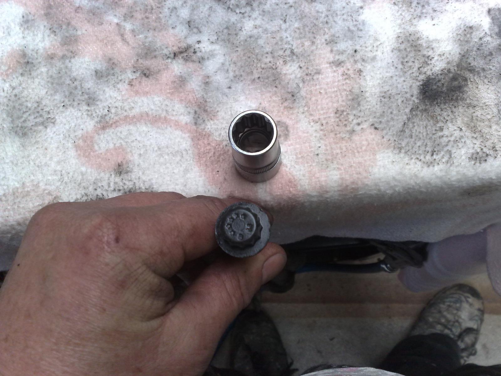
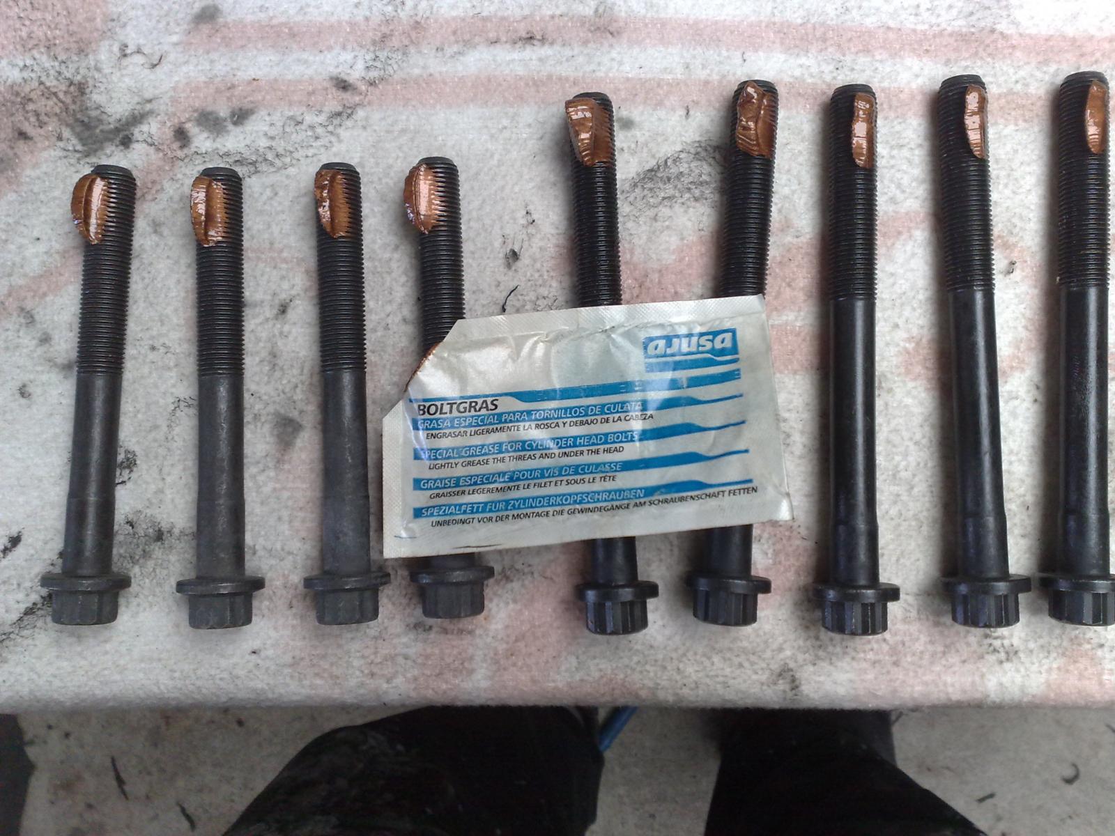
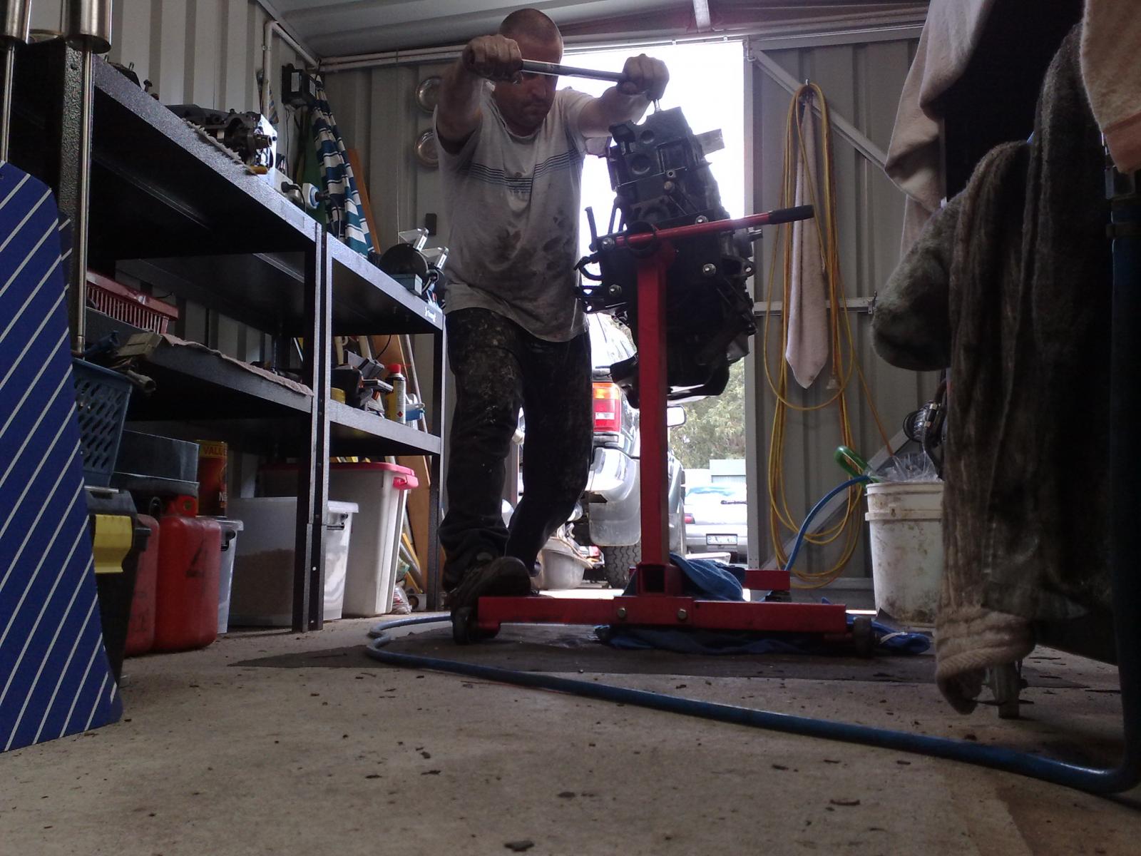
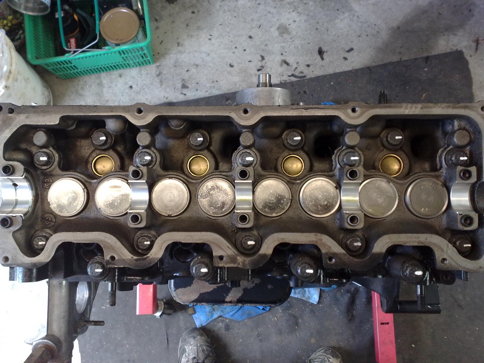
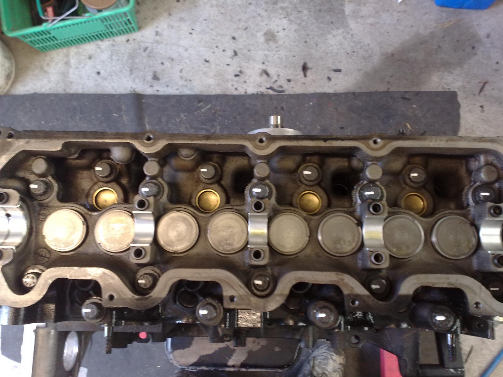
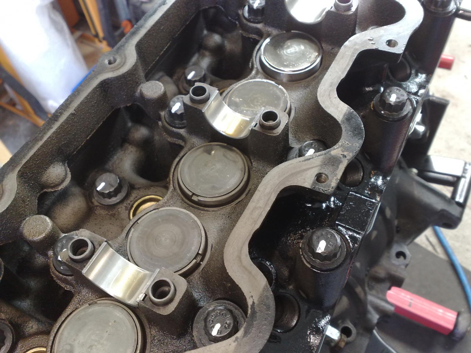
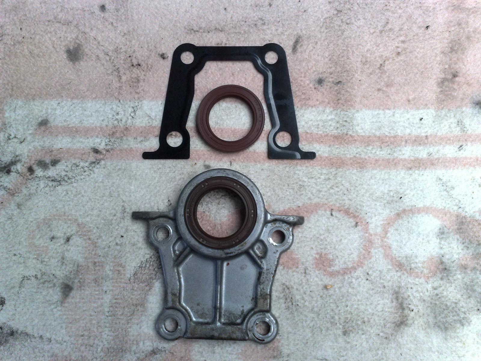
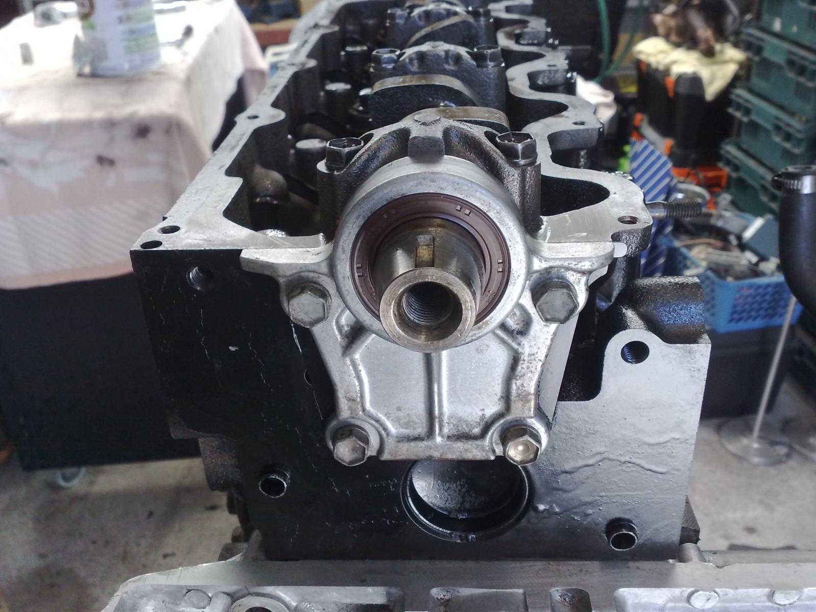
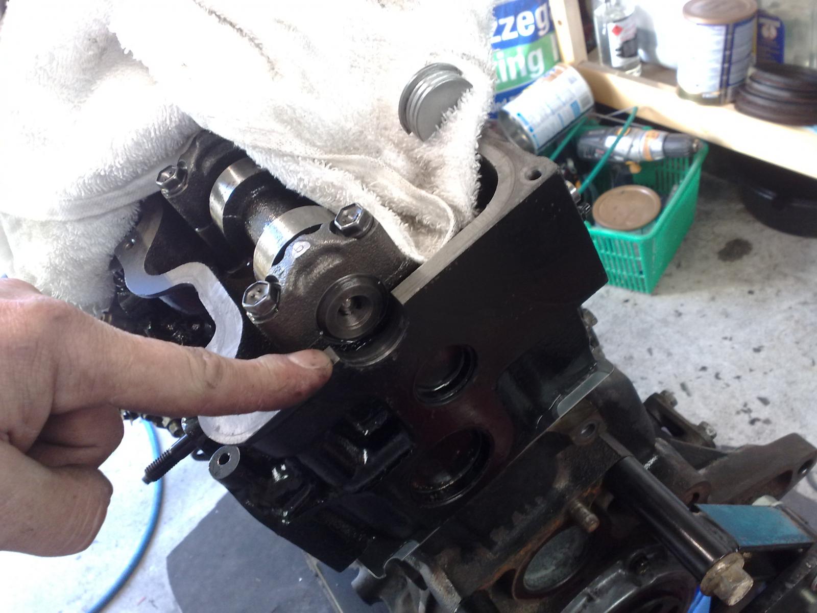
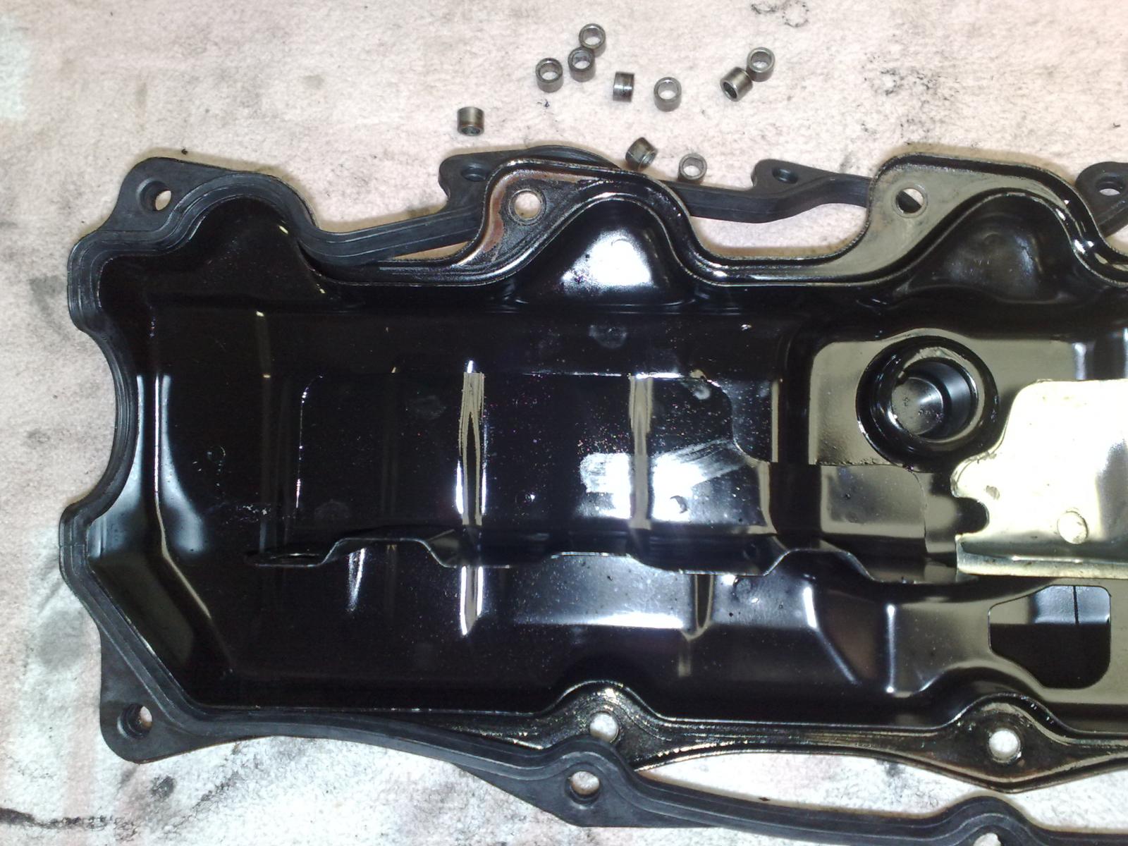
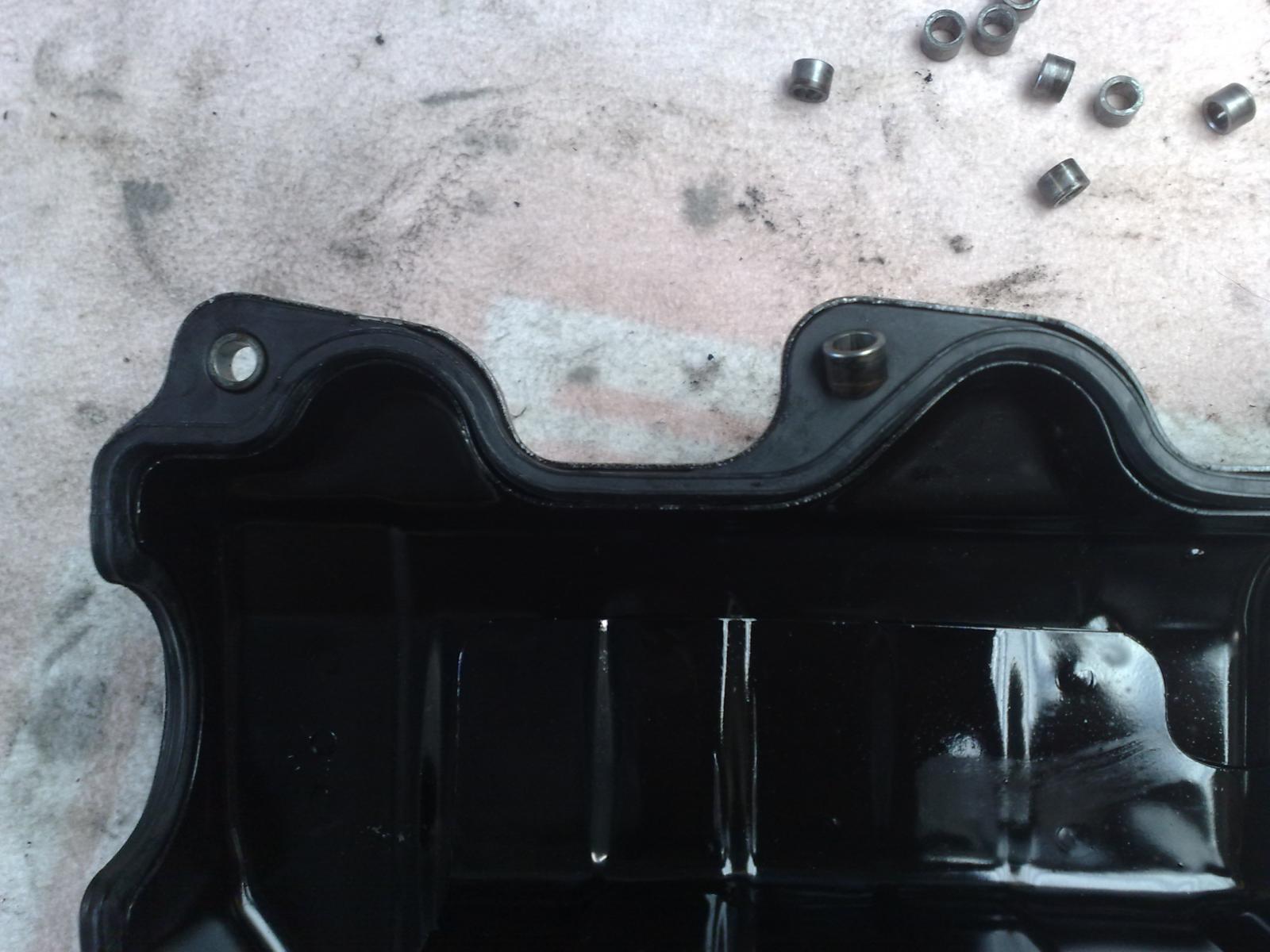
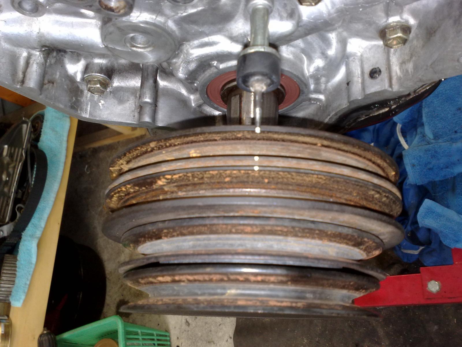
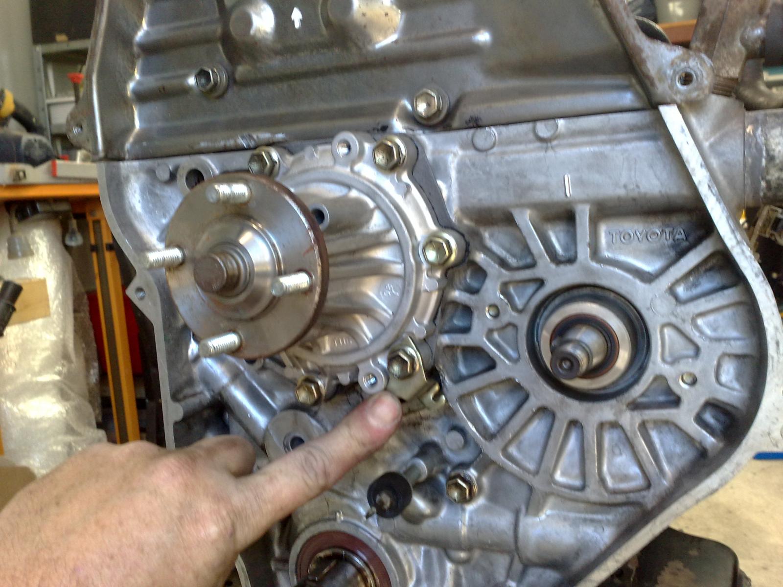
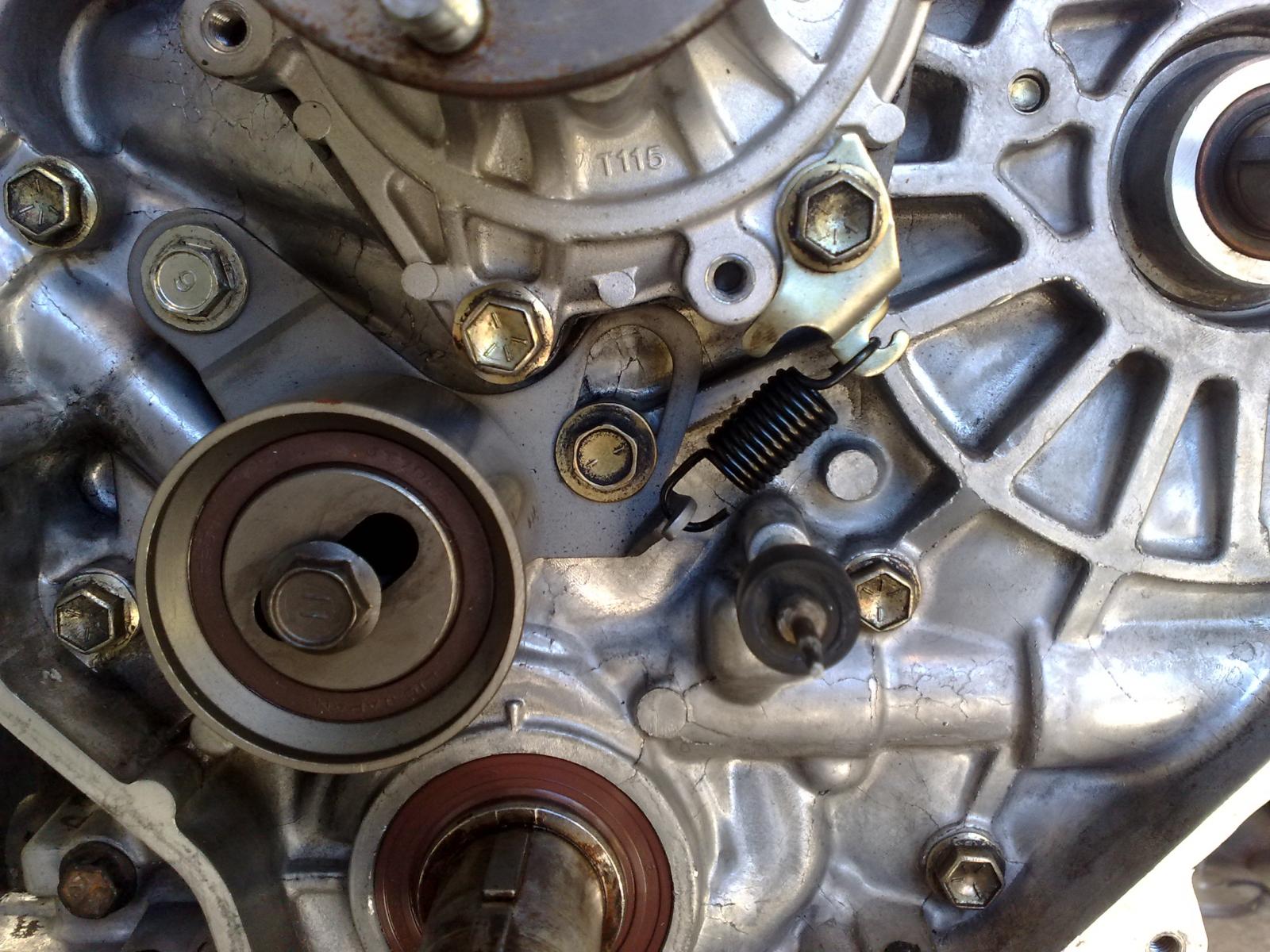
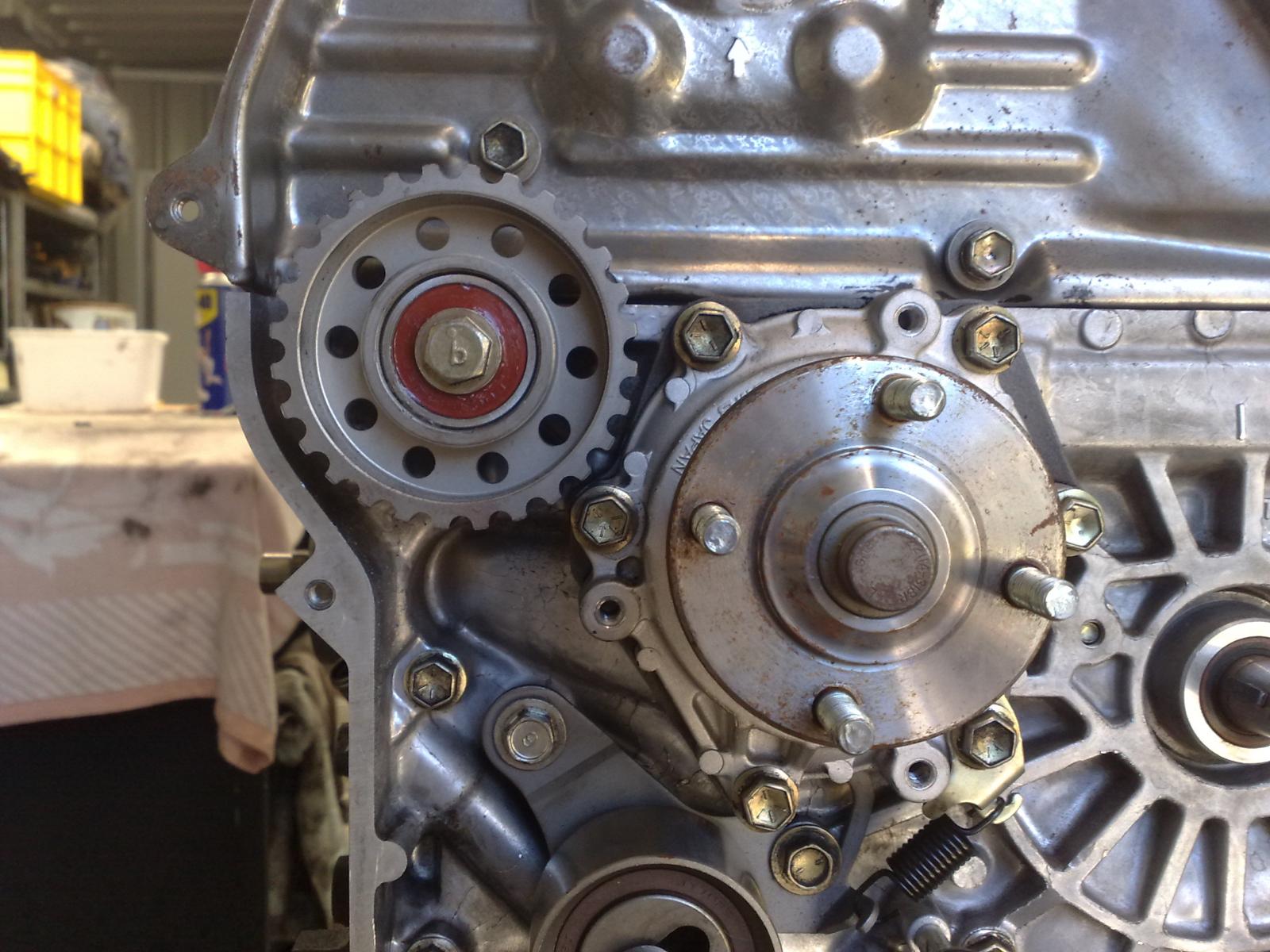
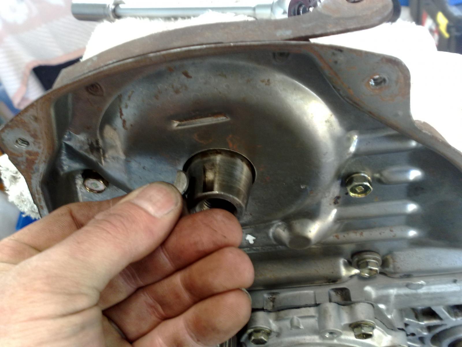
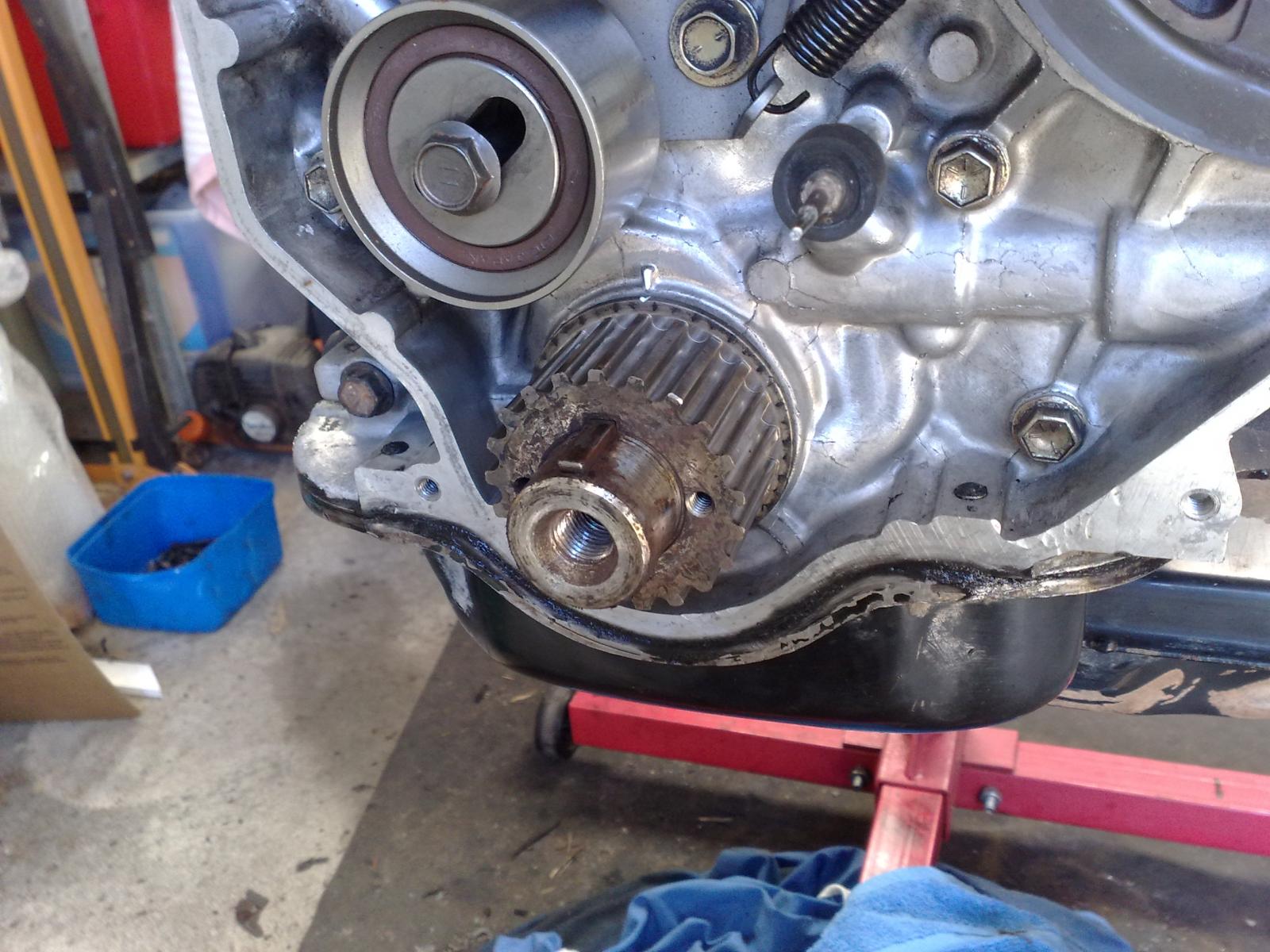
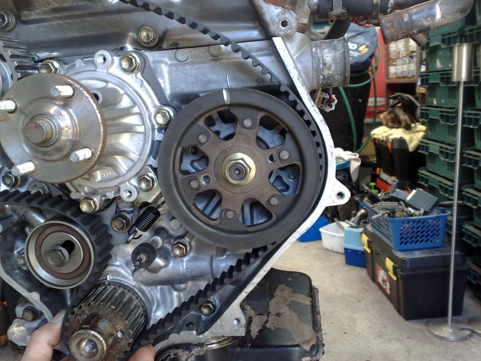
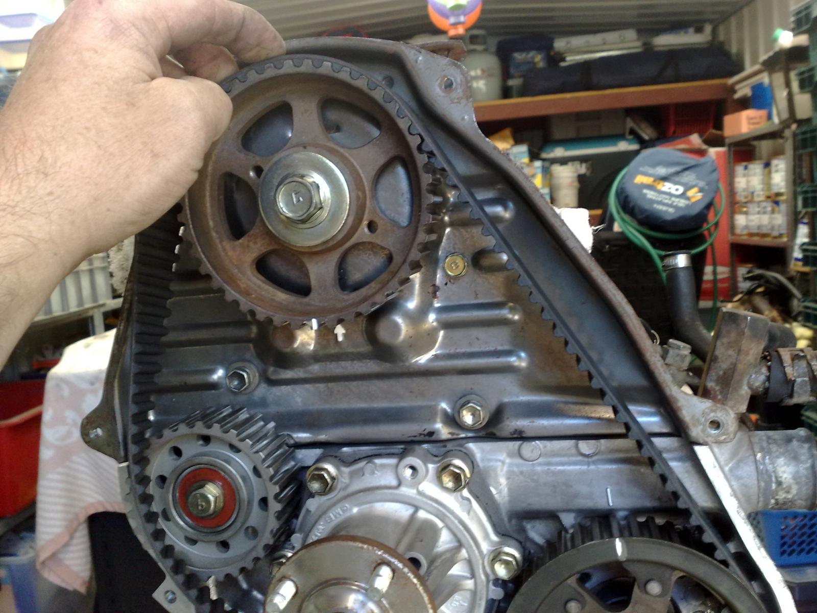
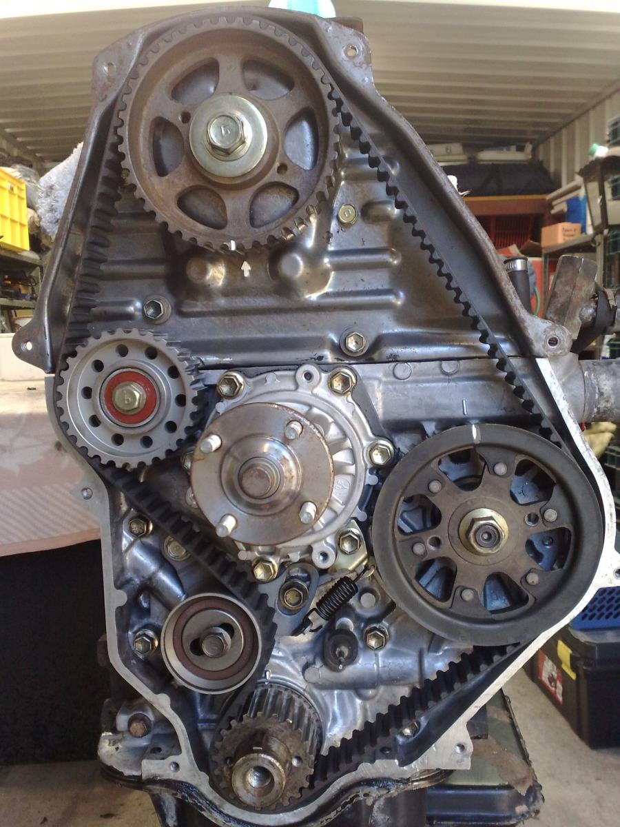
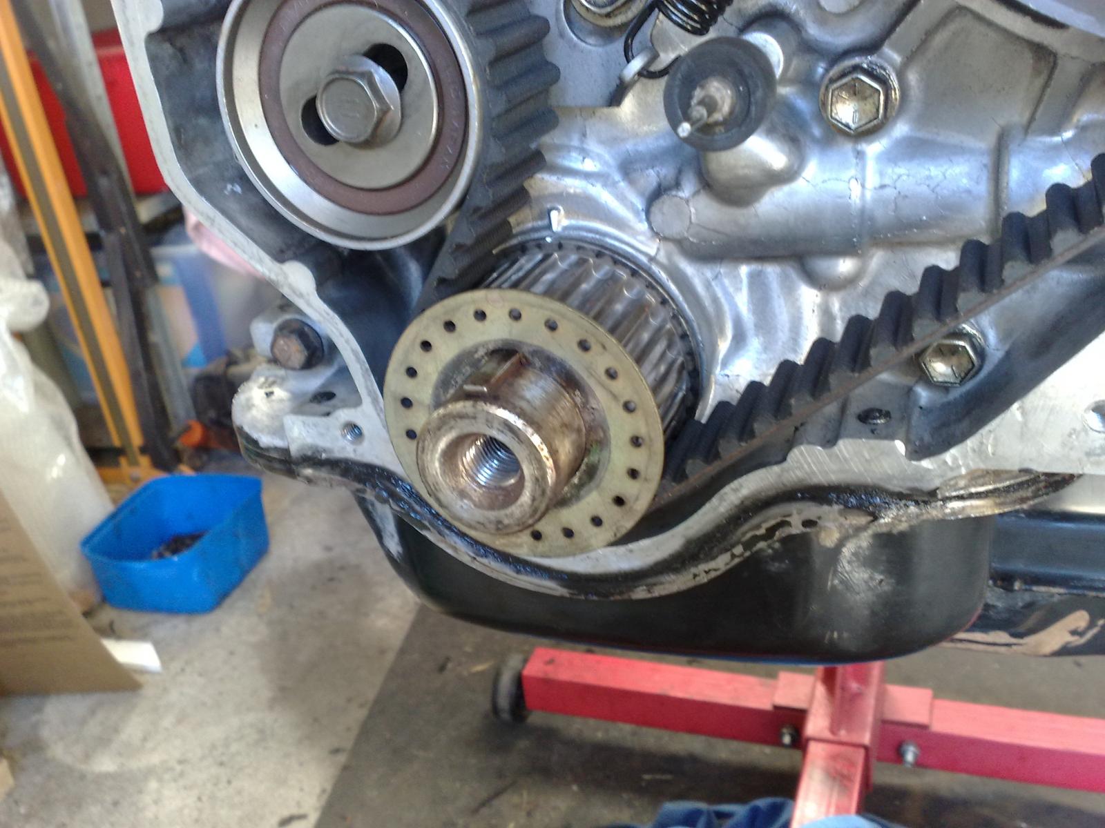
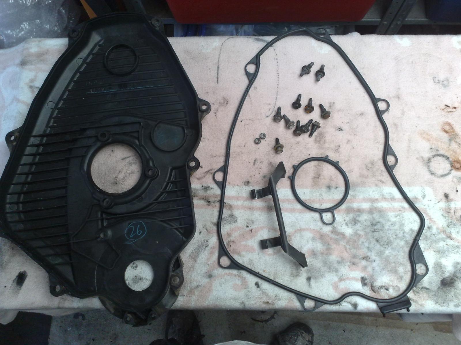
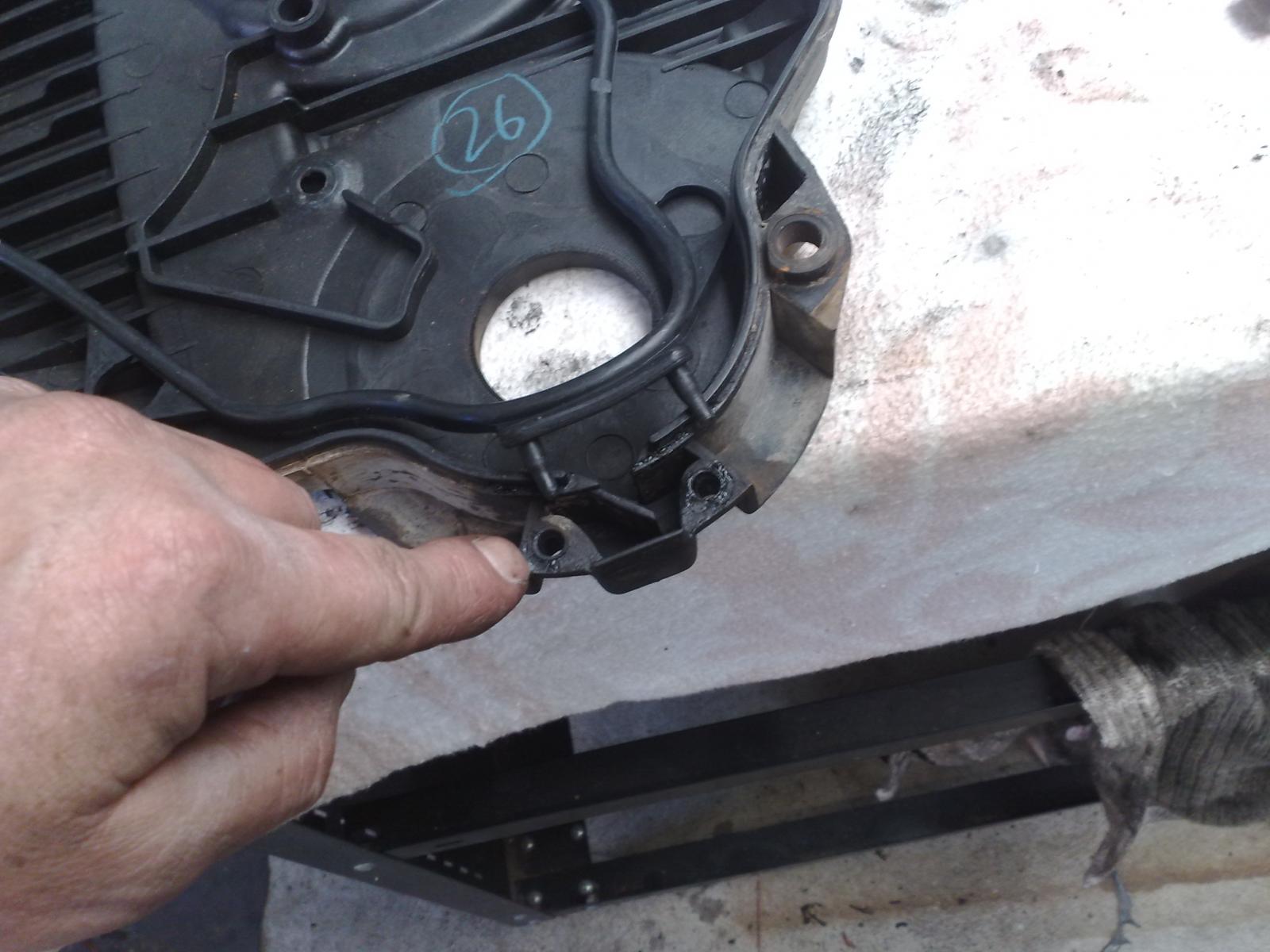
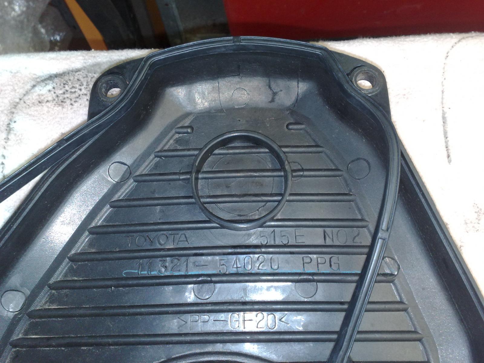
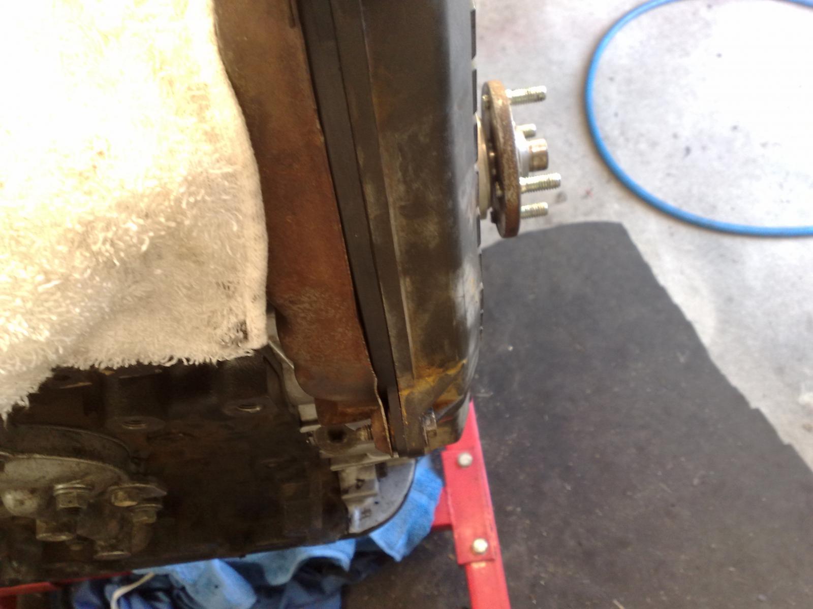
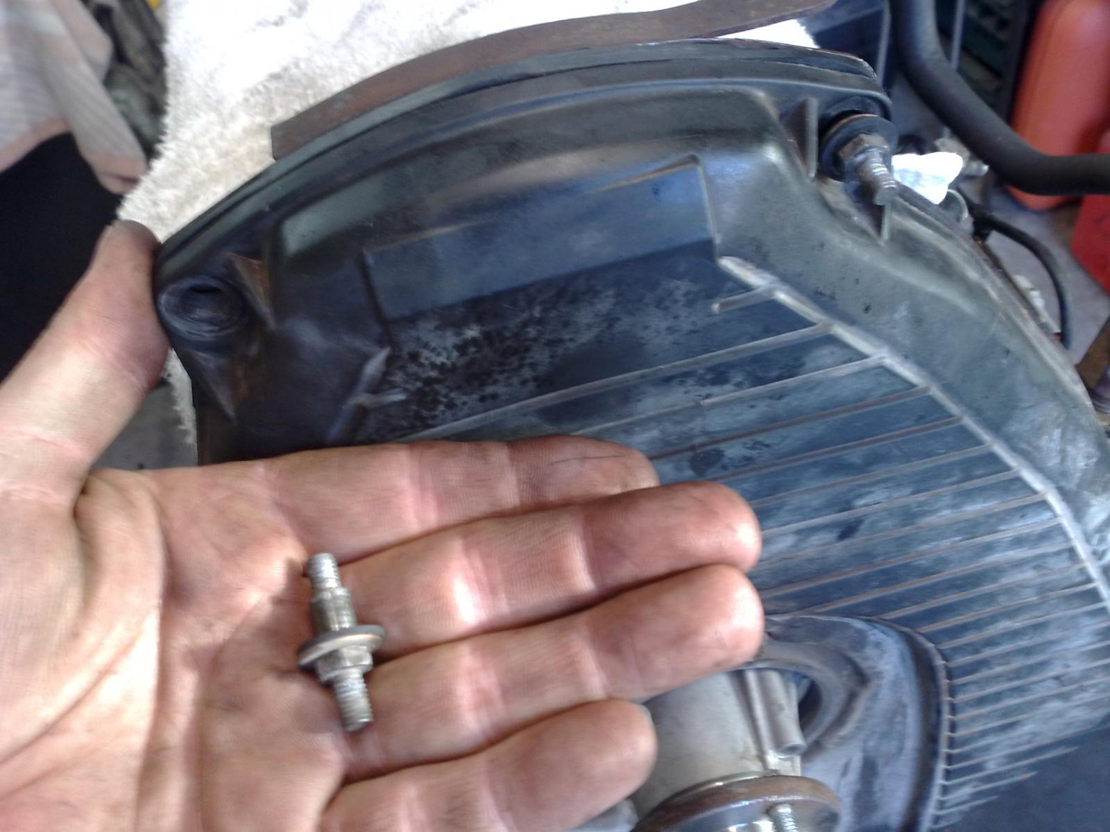
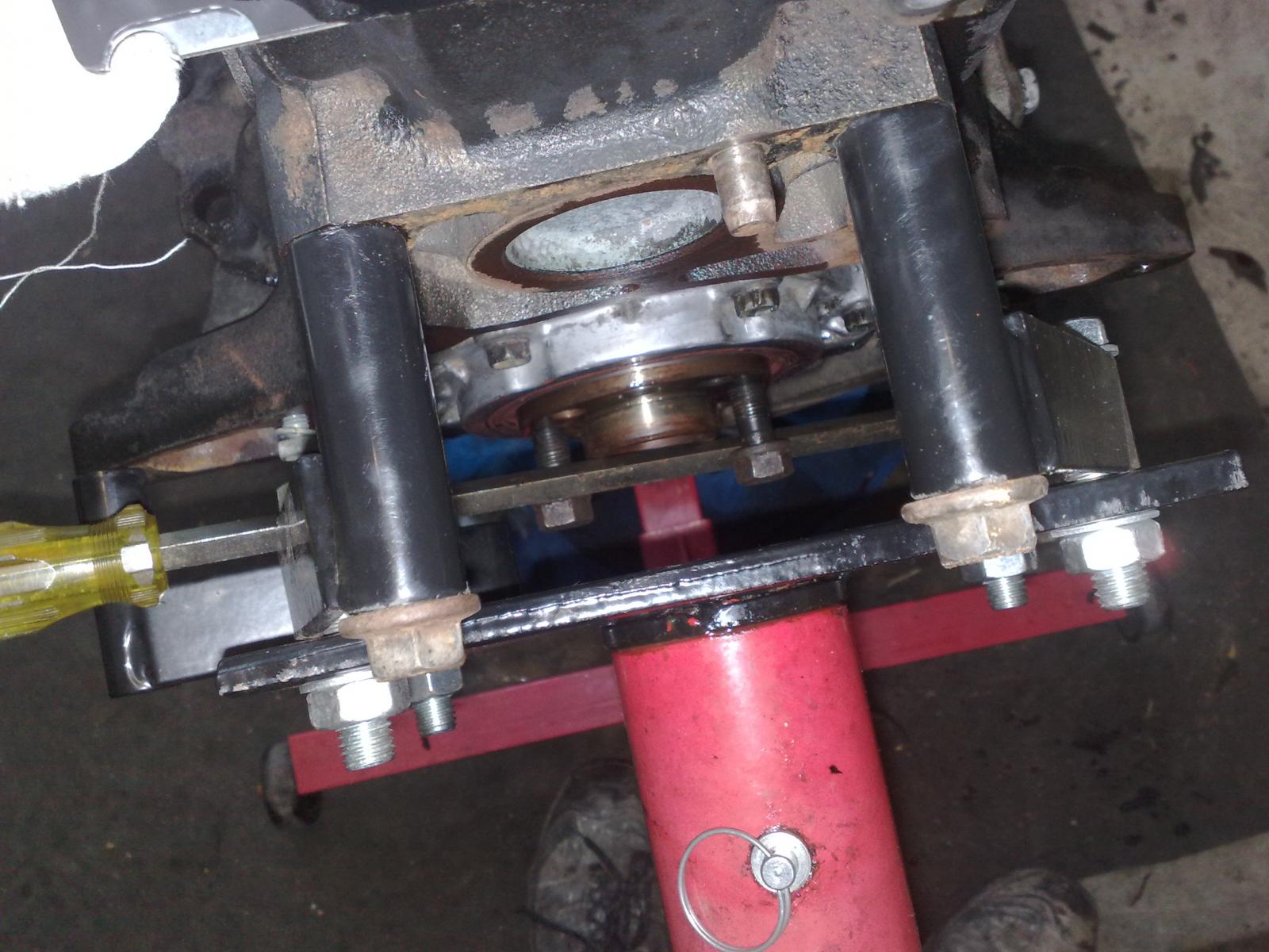
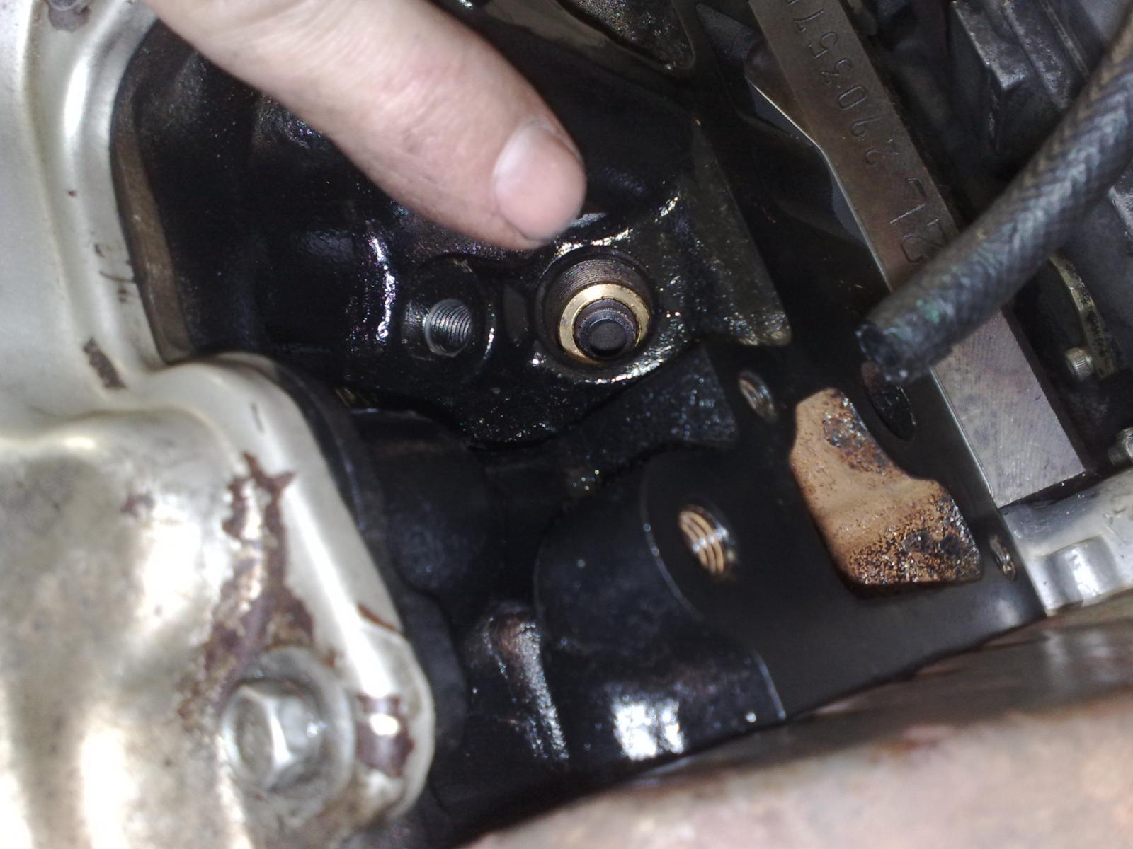
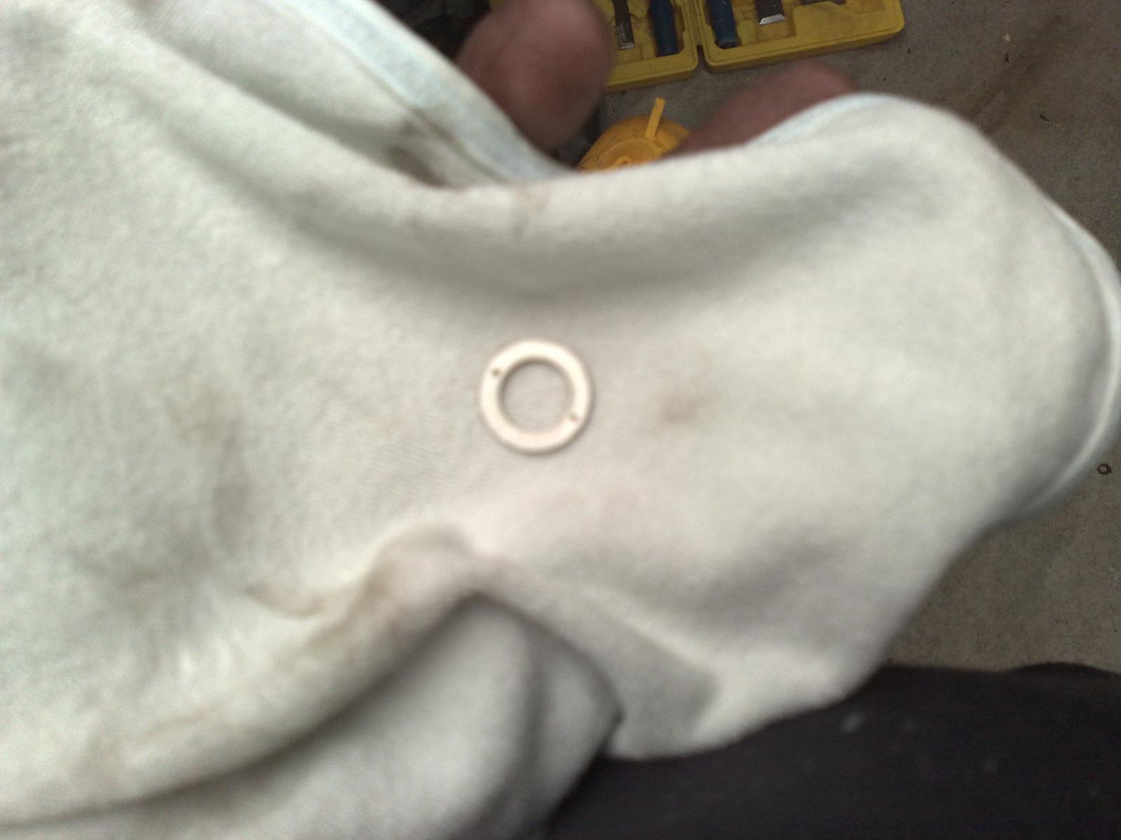
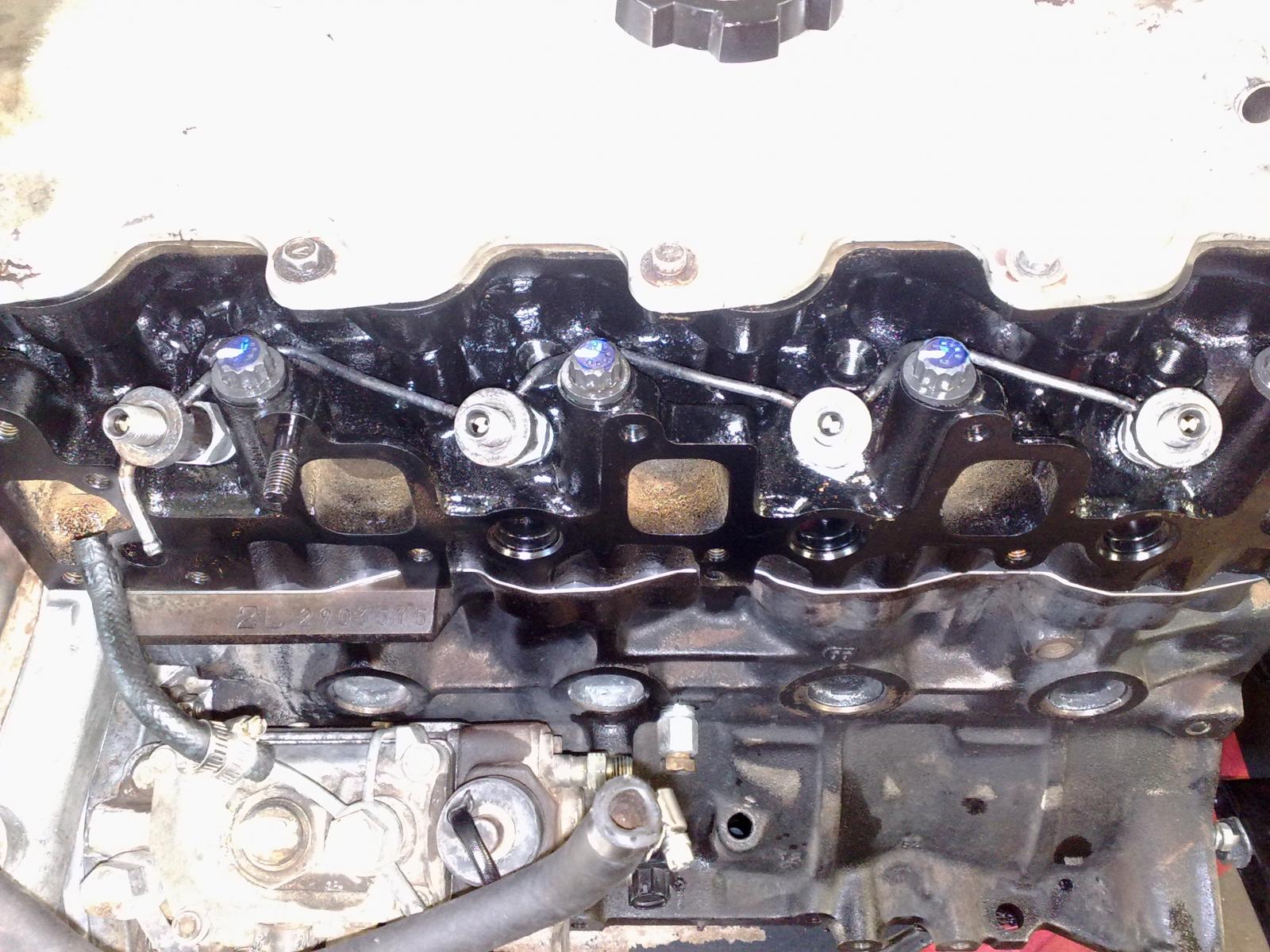
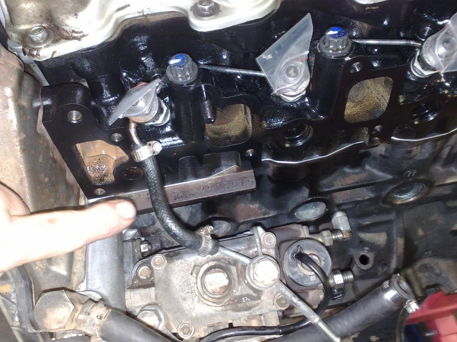
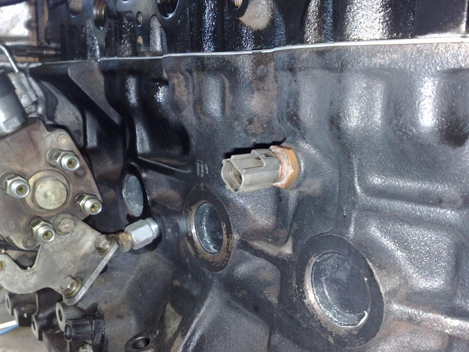
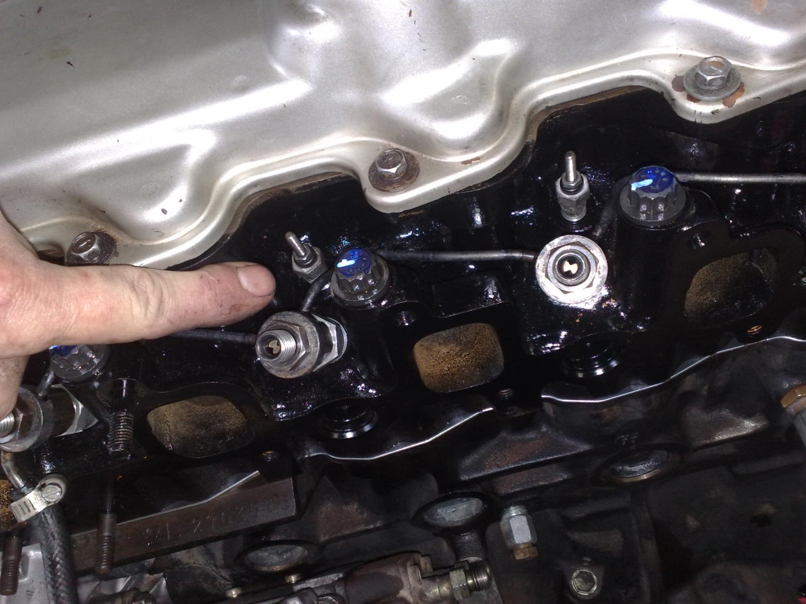
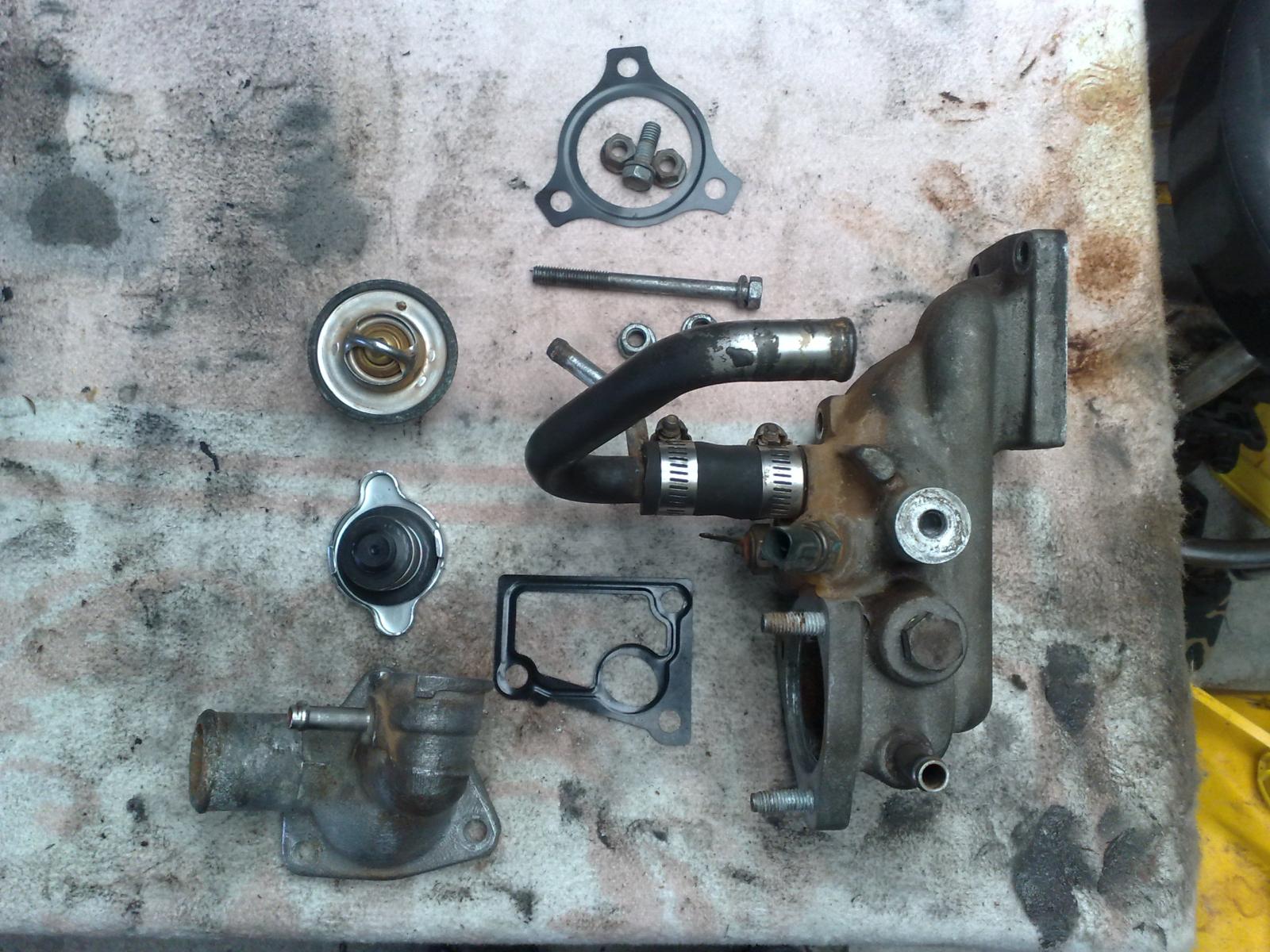
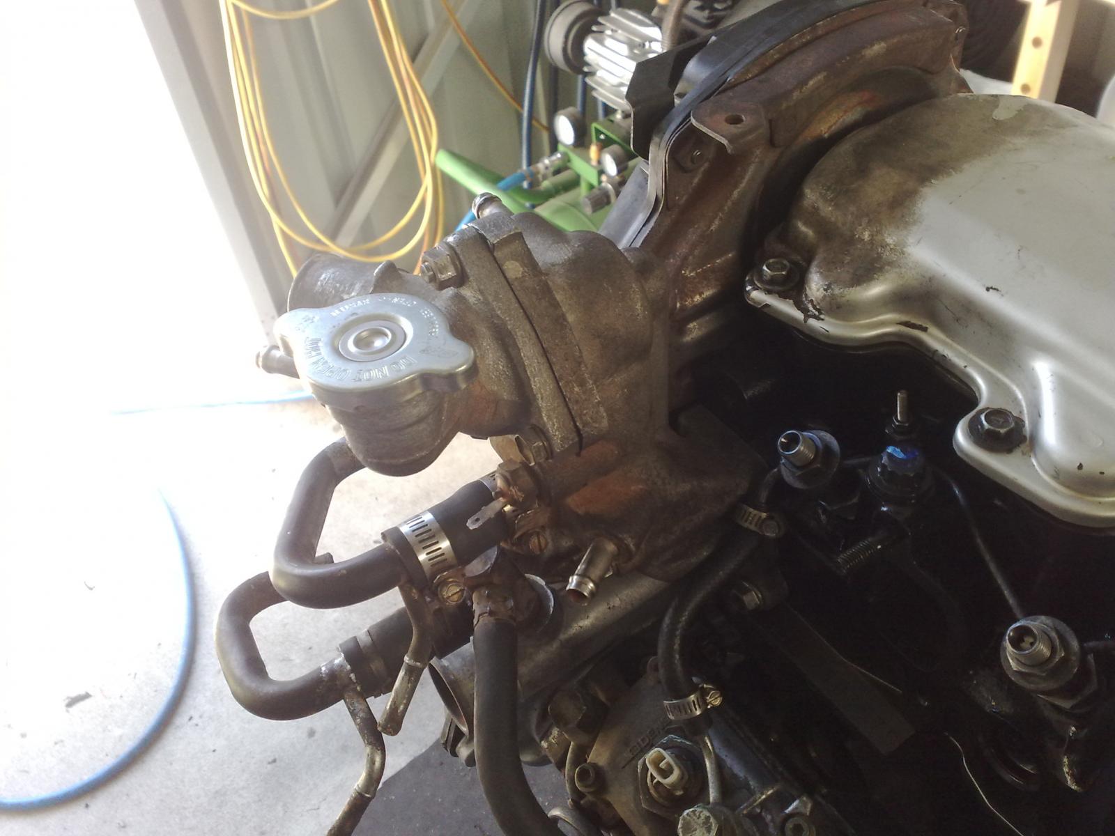
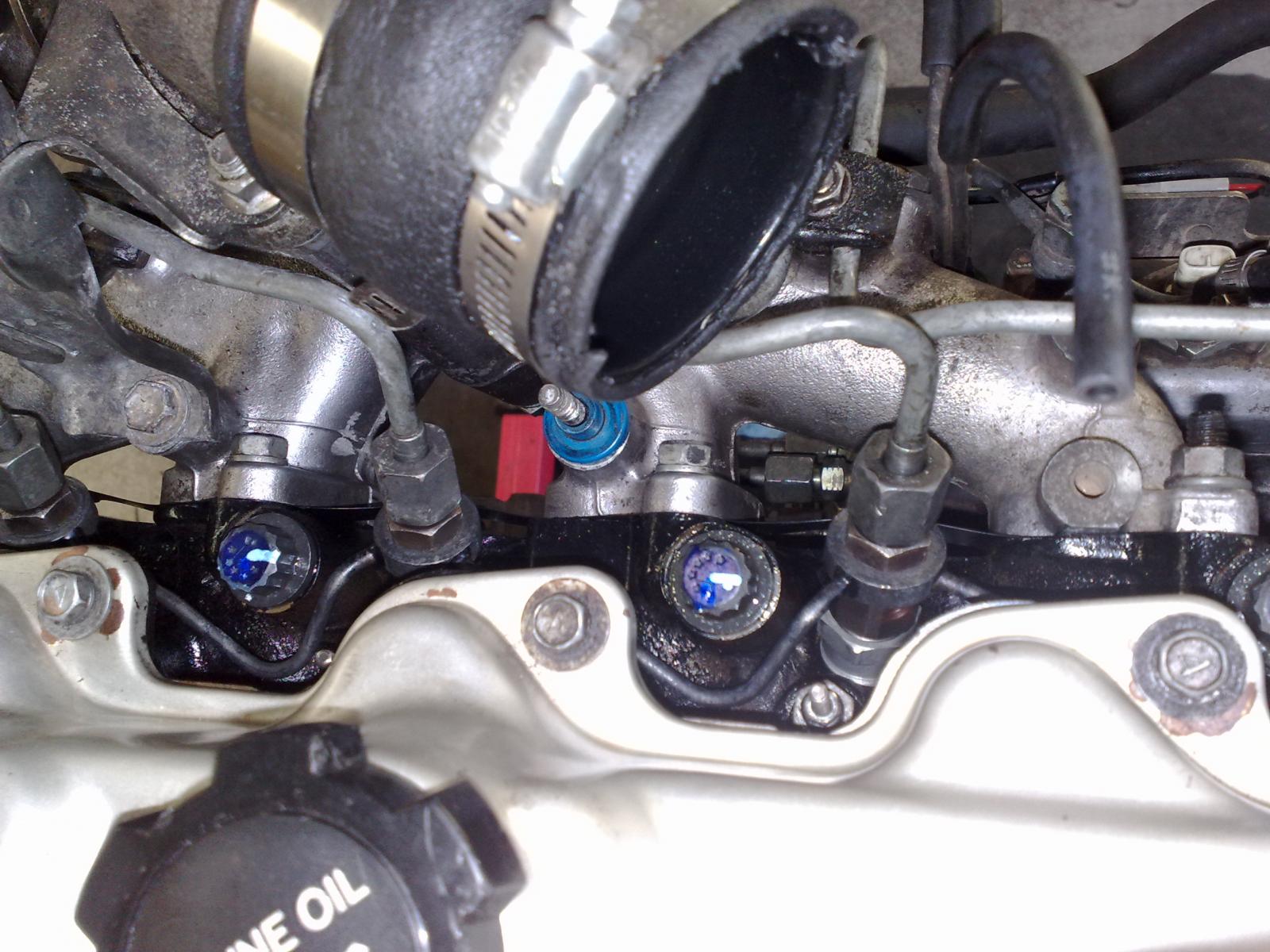
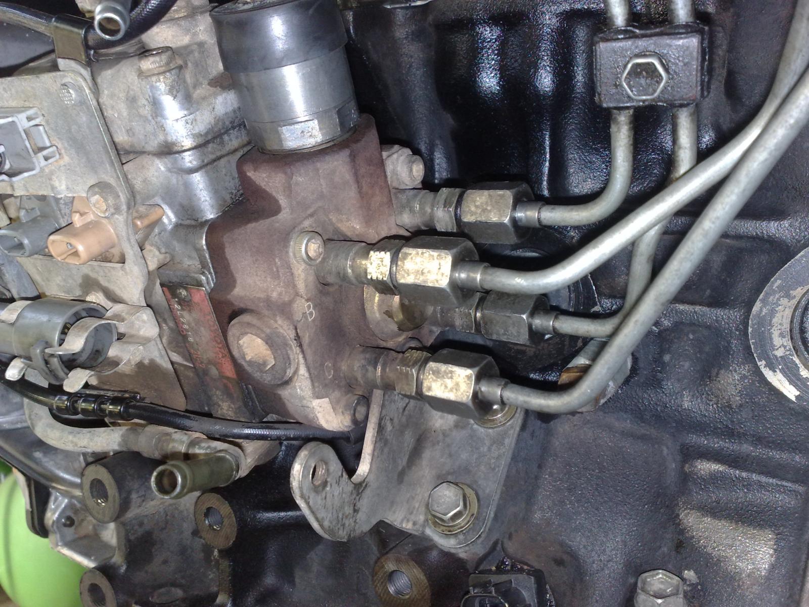
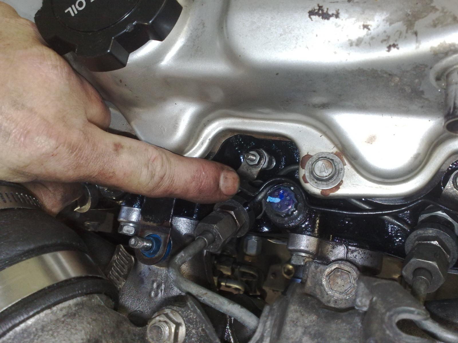
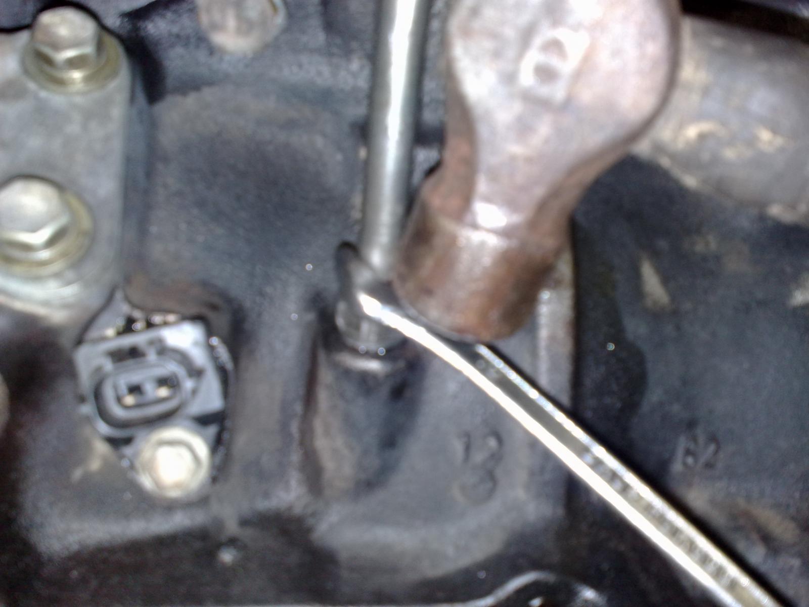
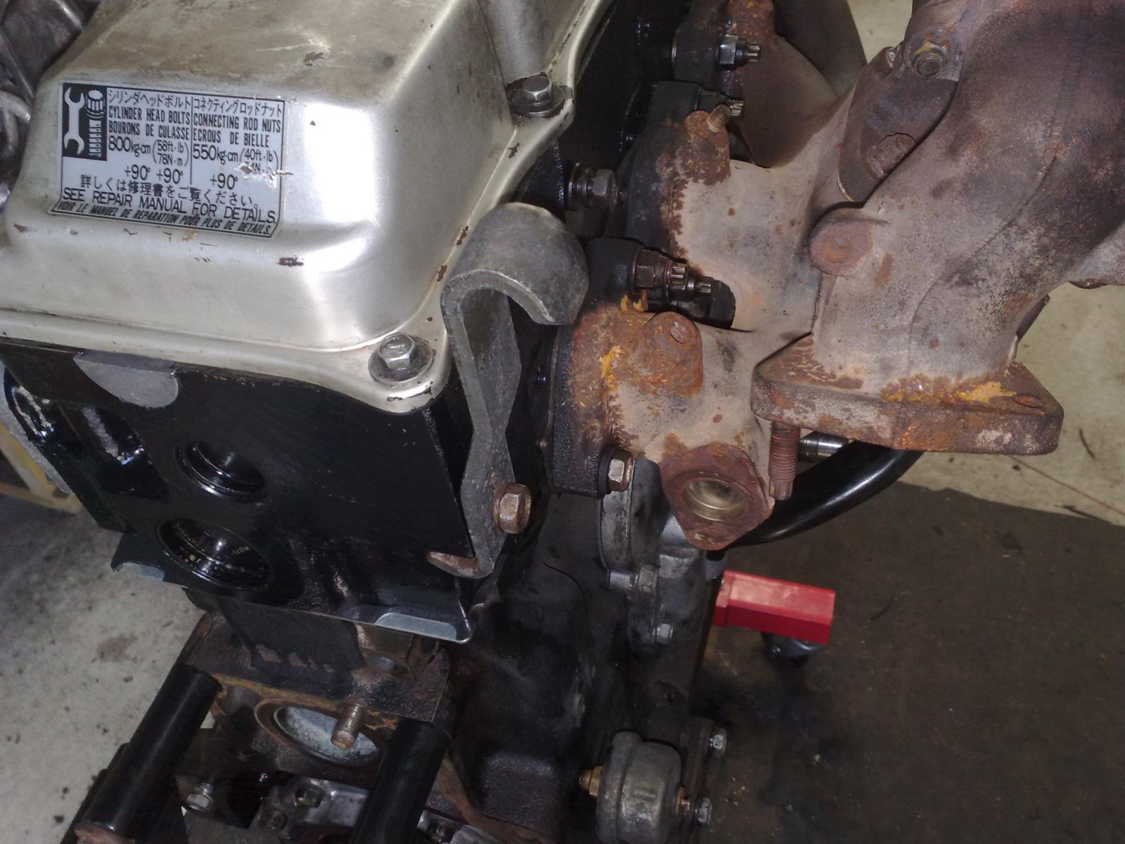